
Subscribe to Our Youtube Channel
Related Manuals for HOMCOM 824-049V80


Summary of Contents for HOMCOM 824-049V80
- Page 1 INcjh022_US 824-049V80 120V~60Hz 45W IMPORTANT, RETAIN FOR FUTURE REFERENCE: READ CAREFULLY ASSEMBLY & INSTRUCTION MANUAL...
- Page 2 READ CAREFULLY BEFORE ATTEMPTING TO ASSEMBLE, INSTALL, OPERATE OR MAINTAIN THE PRODUCT DESCRIBED. PROTECT YOURSELF AND.OTHER BY OBSERVING ALL SAFETY INFORMATION. FAILURE TO COMPLY WITH INSTRUCTIONS COULD RESULT IN PERSONAL INJURY AND/OR PROPERTY DAMAGE! IMPORTANT SAFETY INFORMATION 1. Read all instructions carefully before using the FAN. 2.
- Page 3 12. Do not use FAN outdoors. 13. Disconnect the fan from the mains power when not in use, and before servicing or performing any maintenance. WARNING The Main Power Switch and the On/Off switch should not be used as the sole means of disconnecting power.
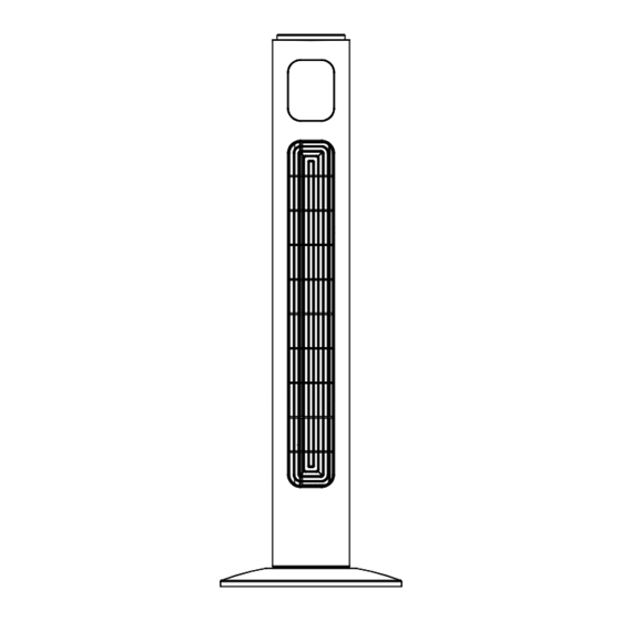
- Page 4 To avoid danger of electric shock, unplug WARNING : from outlet when not in use and before cleaning. If the supply cord is damaged, it or it’s must be replaced by the manufactory service agent or a similarity qualified person in order to avoid a hazard. PARTS NAME Control Panel LED Display...
- Page 5 Thread the power supply cord through the two cut-outs at the bottom of the base.. (shown in Fig 1) ( Fig 1) REMOTE CONTROL Included a button cell battery (the type of battery CR2025). The Remote Control Power button is labeled as such. All the functions performed with the Remote Control work identically to the Manual Controls.
- Page 6 shown in Fig 3) or by your remote control (shown in Fig 2). 1. Place the FAN on a stable flat surface. Plug the cord set into a 120V~ electrical outlet. Plug on the FAN, existing room temperature will be displayed at display panel.
- Page 7 display. 6. OSC : Pressing the ‘OSC’ button will start and stop the oscillation function. The symbol is displayed on the LED screen.(shown in Fig 5) ( Fig 4 ) DISPLAY LED-C an be switched off temporarily by press the LED button on the remote or by pressing and holding the SPEED button on the control panel for more than 3 seconds, the display will light up again once any control button is activated.
- Page 8 2. If the unit requires external cleaning make sure it is switched off and unplugged from the mains supply. Use a soft tissue or cloth for general cleaning. To remove more persistent dirt or grime wipe down with a cloth that has been dampened with warm soapy water.
Need help?
Do you have a question about the 824-049V80 and is the answer not in the manual?
Questions and answers