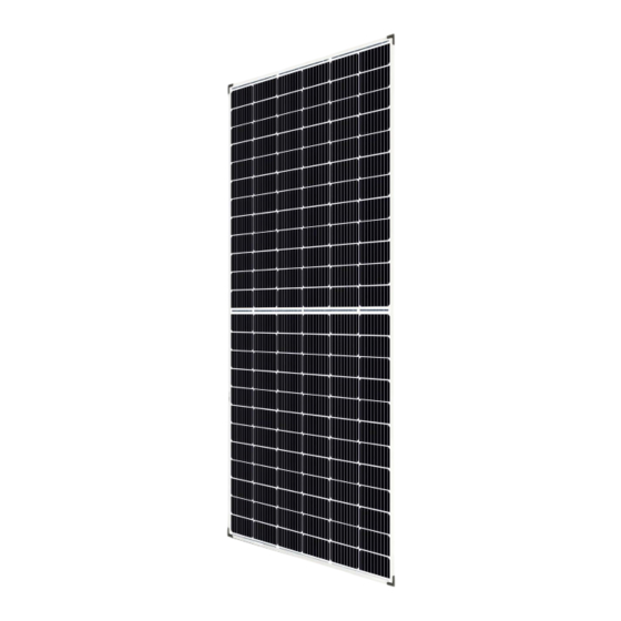
Summary of Contents for CanadianSolar CS3U-MS-FG
- Page 1 All manuals and user guides at all-guides.com INSTALLATION MANUAL OF DYMOND MODULE For professional use only...
-
Page 2: Table Of Contents
All manuals and user guides at all-guides.com GENERAL INFORMATION INSTALLATION MANUAL DISCLAIMER LIMITATION OF LIABILITY SAFETY PRECAUTIONS INFORMATION PURSUANT TO ART. 33 OF THE REACH REGULATION MECHANICAL / ELECTRICAL SPECIFICATIONS UNPACKING AND STORAGE MODULE INSTALLATION MODULE WIRING MODULE GROUNDING MOUNTING INSTRUCTIONS | 10 MAINTENANCE | 10... -
Page 3: General Information
This manual is only valid for the double glass been connected. module type CS3U-MS-FG, CS3U-P-FG, CS3K-MS-FG, CS3K-P-FG, CS6K-P-FG, CS6X-P-FG, CS6K-M-FG, CS6K- Avertissement: Toutes les instructions devront MS-FG and CS6X-M-FG. -
Page 4: Information Pursuant To Art. 33 Of The
All manuals and user guides at all-guides.com connector. Regulation”), we inform you that our solar modules contain a Substance of Very High Concern (“SVHC”) Do not allow children and unauthorized in a concentration above 0.1 % (weight by weight). persons near the installation site or storage area of modules. -
Page 5: Unpacking And Storage
(roof, facade, in turn may compromise module reliability and support, etc.) can bear the module system load. void Canadian Solar Inc’s warranty. · Canadian Solar Inc. double glass solar modules www.canadiansolar.com... - Page 6 All manuals and user guides at all-guides.com have been qualified for Application Class A conditions appearing in nature - temperature and (equivalent to Safety Class II requirements). humidity. Modules rated under this class should be used in systems operating at voltage above 50 V or power ·...
-
Page 7: Module Wiring
This also enables condensation or moisture to dissipate. · According to UL 1703, any other specific clearan- ce required for maintaining a system fire rating www.canadiansolar.com... - Page 8 All manuals and user guides at all-guides.com Table 1: System Cable Scheme for CS3U and CS3K modules Module types Standard cables Optional cables CS3U-MS-FG, CS3U-P-FG, CS3K-MS-FG, CS3K-P-FG Leap-frog The maximum distance between two adjacent cuit voltage. module frames should be within 50 mm (1.96 in) for side with mounting clamps, and within 25 mm (0.98...
-
Page 9: Mounting Instructions
One buffer rubber material (Recommended material is EPDM) must be added between the clamp and the glass. · Canadian Solar Inc. warranty may be void in cases Rail Bolt Bottom End Clamp Glass where improper clamps or unsuitable installation www.canadiansolar.com... -
Page 10: Maintenance
All manuals and user guides at all-guides.com 10 | · The module is only considered to comply with IEC 61215 and UL 1703 when mounted as speci- AMENDED EDITIONS fied in the instructions in ANNEX B. Any module AND DATES without a frame (laminate) shall not be conside- red to comply with the requirements of UL 1703 unless the module is mounted with hardware... - Page 11 32.3 9.14 39.1 9.73 x 0.23 in) CS3K-300MS-FG 32.5 9.24 39.3 9.82 Without (52.9 junction- lbs) CS3K-305MS-FG 32.7 9.33 39.5 box and CS3K-310MS-FG 32.9 9.43 39.7 9.98 corner CS3K-315MS-FG 33.1 9.52 39.9 10.06 protector CS3K-320MS-FG 33.3 9.61 40.1 10.14 www.canadiansolar.com...
- Page 12 All manuals and user guides at all-guides.com 12 | Maximum Operating Operating Open Circuit Short Circuit Max. Series Overall Weight Module Type Power voltage current Voltage Current Fuse Dimension <kg> Pmax <W> Vmp <V> Imp <A> Voc <V> Isc <A> Rating <A>...
- Page 13 8.61 45.6 9.13 (60.6 junction- lbs) CS6X-325M-FG 37.4 8.69 45.8 9.21 box and corner CS6X-330M-FG 37.5 45.9 9.31 protector CS6X-335M-FG 37.8 8.87 46.1 9.41 CS6X-340M-FG 37.9 8.97 46.2 9.48 CS6X-345M-FG 38.1 9.06 46.4 9.56 CS6X-350M-FG 38.3 9.14 46.6 9.67 www.canadiansolar.com...
- Page 14 All manuals and user guides at all-guides.com 14 | ANNEX B: FRAMELESS DYMOND MODULE INSTALLATION MANUAL SUPPLEMENT All the basic requirements of the main applicable standards, location and local installation manual should apply to this climate. Determination of the design loads supplement, unless otherwise specified.
- Page 15 Uplift load ≤2400 Pa clamp length=80 mm see illustration B six clamps, GS-IC (Middle clamp)/ A=250±20 mm, Downforce load≤5400 Pa 2-D-4 GS-EC (End clamp), VDE / CSA B=579±20 mm, Uplift load ≤2400 Pa clamp length=100 mm see illustration B www.canadiansolar.com...
- Page 16 All manuals and user guides at all-guides.com 16 | Mounting Clamp Quantity & Certification Supplier Clamp Image Clamp Type & length Load (Pa) Method Location Body PW-CS-01(End clamp) / four clamps, Downforce load≤2400 Pa 2-E-1 PW-CS-02 (Middle clamp), A=380±20 mm, VDE / CSA Uplift load ≤2400 Pa clamp length=100 mm...
- Page 17 Uplift load ≤2400 Pa clamp length=100 mm see illustration B six clamps, GS-IC (Middle clamp) A=300±20 mm, Downforce load≤5400 Pa 3-D-4 / GS-EC (End clamp), VDE / CSA B=684±20 mm, Uplift load ≤2400 Pa clamp length=130 mm see illustration B www.canadiansolar.com...
- Page 18 All manuals and user guides at all-guides.com Mounting Clamp Quantity Certification Supplier Clamp Image Clamp Type & length Load (Pa) Method & Location Body PW-CS-01(End clamp) / four clamps, Downforce load≤2400 Pa 3-E-1 PW-CS-02 (Middle clamp), A=440±20 mm, VDE / CSA Uplift load ≤2400 Pa clamp length=130 mm see illustration A...
- Page 19 Technology A=380±20 mm, VDE / CSA clamp), Uplift load ≤2400 Pa see illustration A (Suzhou) Co.,Ltd. clamp length=200 mm The following clamps in table 5 have been approved as compatible with Canadian Solar double glass module CS3U-MS-FG and CS3U-P-FG. www.canadiansolar.com...
- Page 20 All manuals and user guides at all-guides.com 20 | Table 5: CS3U-MS-FG and CS3U-P-FG compatible clamps Mounting Clamp Quantity Certification Supplier Clamp Image Clamp Type & length Load (Pa) Method & Location Body K2 Systems GmbH K2 frameless clamp, four clamps, Downforce load≤5400 Pa...


Need help?
Do you have a question about the CS3U-MS-FG and is the answer not in the manual?
Questions and answers