Shure AXT630 - Antenna Distribution System Manual
- User manual (37 pages) ,
- Manual (12 pages) ,
- User instructions (11 pages)
Advertisement
- 1 General Description
- 2 Mounting Instructions
- 3 Controls and Connectors
- 4 Antennas
- 5 RF Output Distribution
- 6 Adding a Spectrum Manager to an Antenna System
- 7 Troubleshooting
- 8 Main Menu
- 9 Utility Menu
- 10 Firmware Updates
- 11 Specifications
- 12 Accessories
- 13 IMPORTANT SAFETY INSTRUCTIONS
- 14 Documents / Resources
General Description
Antenna Distribution Systems send the RF signal from a single pair of antennas to multiple receivers. Ultra-linear amplification and adjustable attenuation optimize performance in difficult RF environments. Selectable input filters match the available frequency bands of transmitters, providing extra protection from strong out-of-band signals. BNC antenna output pairs distribute bandfiltered signals to up to 4 receivers. A pair of wideband cascade ports supply wideband RF signals to Spectrum Managers or additional antenna distribution amplifiers. Networking allows Wireless Workbench to control filtering ranges and attenuation. For added flexibility, Axient Antenna Distribution Systems are compatible with Shure ULX-D and UHF-R receivers.
To maximize use of the RF spectrum, Antenna Distribution Systems are available in the following frequency ranges:
- AXT630 (470-698 MHz)
- AXT631 (606-814 MHz)
- AXT632 (470-510 MHz and 630-787 MHz)
Note: Instructions in this system guide apply all models of Axient Antenna Distributions Systems.
Features
- Selectable input filtering provides system-wide protection against strong out-of-band signals
- Wideband filtering option covers multiple bands
- Up to 15 dB of selectable RF attenuation for signal-to-noise optimization
- Front panel interface and Wireless Workbench 6 software control provide easy setup and control of filtering, antenna power, and attenuation
- BNC outputs: 4 antenna output pairs
- Wideband RF cascade port with selectable 3 dB make-up gain for connecting wideband devices
- Ethernet Networking: 2 PoE enabled Ethernet ports
- IEC power ports enable daisy-chaining of AC power
Mounting Instructions
This component is designed to fit into an audio rack.


To prevent injury this apparatus must be securely attached to the rack.
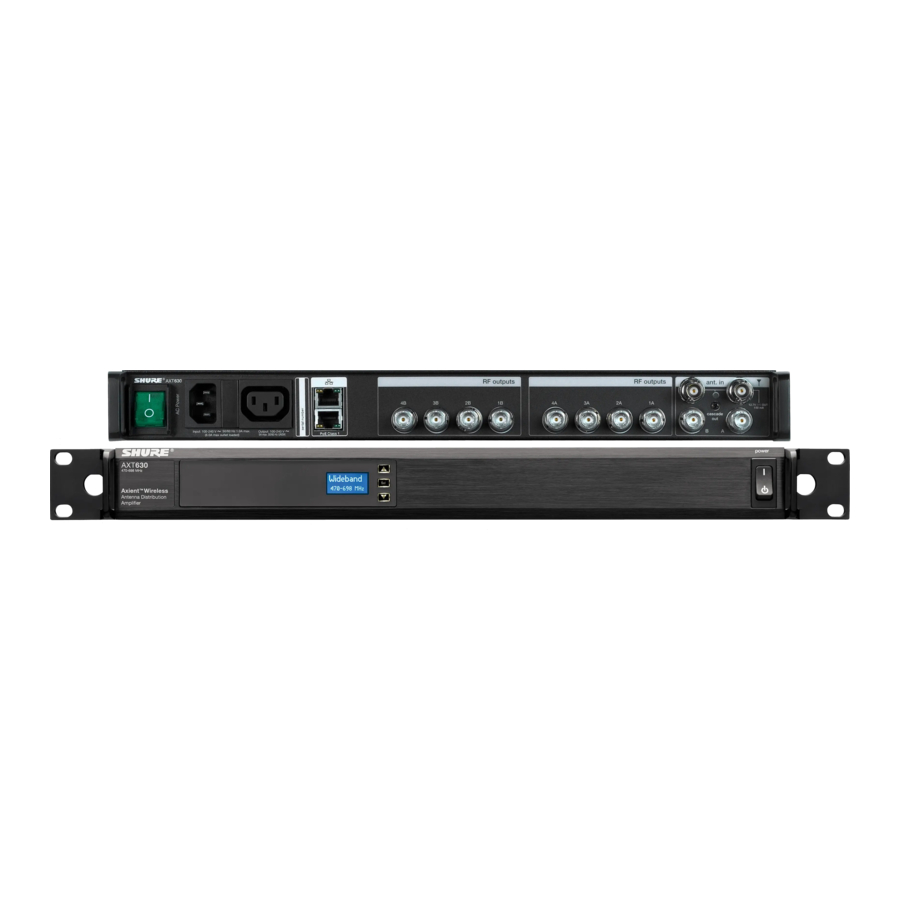
Controls and Connectors

- LCD Display
Displays menu and settings. - Navigation Buttons
- Arrows: Scroll menus and change settings
- Set: Enables menu edits and saves changes
Tip: Press and hold the Set button for 1 second to activate the Hardware Identify feature in Wireless Workbench.
- Power Switch
Powers the unit on or off - AC Power Primary Switch
AC Main Power Switch - AC Power
In IEC Connector, 100-240 V AC - AC Power Cascade
Use the IEC extension cables to connect up to 5 devices to a single AC power source. - Network Speed LED (amber):
- Off = 10 Mbps
- On = 100 Mbps
- Ethernet Ports (2)
PoE Class 1 enabled. Connect to an Ethernet network to enable remote control and monitoring - Network status LED (green)
- Off = no network link
- On = network link active
- Flashing = network link active, flash rate corresponds to traffic volume
- RF Output Connectors, Channel B
Distributes RF signal for Channel B - RF Output Connectors, Channel A
Distributes RF signal for Channel A - Antenna IN Ports, Channels A and B
Antenna inputs are DC biased for use with active antennas or in-line amplifiers. - RF Cascade Ports, Channels A and B
Passes the wideband RF signal from one device to the next, allowing up to 5 devices to share a single pair of antennas. - Antenna Input Status LED
- Green = DC power on
- Off = DC power off
- Red = Antenna fault or over-current condition
Antennas
The Antenna Distribution Systems are compatible with front-mounted antennas or with remote-mounted antennas.
Note: When using the input band filtering function, select an antenna with bandwidth to cover the filter range.
Installing Front-mounted Antennas
Mounting the antennas on the front panel improves system performance by providing a clear signal path for the RF signal. Use the supplied bulkhead adapter kit to install the antennas on the front panel.
- Insert the bulkhead adapters on the supplied front-mounting cables through the holes in each bracket and secure them from the front using the supplied hardware.
- Connect the supplied antennas cables to the antenna input BNC connectors.
- Install the antenna onto the bulkhead adapters.
Note: To minimize the possibility of signal dropout and optimize performance, point the antennas up and away from each other at 45° from vertical.
Installing Remote Antennas
Remote antennas offer greater flexibility for antenna placements and can improve performance by providing a less obstructed transmission path and extending range. Consult for tips and best practices for remote mounting antennas.
RF Output Distribution

The RF outputs distribute the signal from a pair of antennas to up to 4 receivers or additional antenna distribution systems. Port-to-port isolation reduces interference, making the distribution ports the best option for distributing signal to additional devices.
Connecting Devices

Connect an A and B pair of RF outputs from the Antenna System to the A and B inputs of the device.
Input Band Filtering
The input band filters act on the RF distribution ports but do not affect the RF cascade ports. The Wideband setting passes the full frequency range of the Antenna Distribution System. Select the band filter that most closely matches the tuning range of connected devices to optimize performance.
When a band filter has been set, operate and tune connected devices within the selected band.
Gain and Attenuation
Use the RF Gain menu to maintain consistent signal levels sent to connected devices. The available adjustment range is -12 to +3 dB when the Cascade ports are off and -15 to 0 dB when the cascade ports are active.
RF Cascade Ports

The RF cascade ports extend the Antenna Distribution System by providing a connection point for additional receivers, Spectrum Managers, or Antenna Distribution Systems.
When Antenna Cascade is set to Auto, the Cascade ports automatically activate when 12 V DC from the antenna input of a connected device is sensed at the port connection. When the cascade ports are active, a signal splitting loss occurs of 5 dB (max.).
Receivers with RF cascade outputs can extend the antenna signal to additional receivers within the same band.
Adding a Spectrum Manager to an Antenna System

Connect the AXT600 Spectrum Manager to the RF Cascade ports of the Antenna Distribution System.
Multiple Levels of Antenna Distribution
For large configurations, multiple Antenna Distribution Systems can be layered to support several levels of signal distribution:

- Two levels of antenna distribution are possible if the level 1 and level 2 Antenna Distribution Systems have the Cascade ports activated
- Up to 3 levels of antenna distribution are possible if only the level 1 Antenna Distribution System has the Cascade ports activated
- For best RF performance, use all the RF outputs on one level before creating additional levels
Level 1: Antenna Distribution System set to Wideband
Level 2: Antenna Distribution System set to a band filter matching the 4 receivers tuned to the same band
Connect the AXT600 Spectrum Manager to the RF cascade ports of the Level 1 Antenna Distribution System
Troubleshooting
Antenna Faults

The antenna input status LED flashes red to indicate a short or over-current condition at an antenna port. To isolate the fault, navigate to the DC power menu. The menu displays which antenna port (A, B, or A+B) is the source of the fault. Check the antenna connections to remove the fault condition.
Over Temperature Message

The Over Temperature message is displayed when the fans are unable to cool efficiently, indicating an elevated temperature condition.
- Press any button to suppress the message for 20 seconds
- Increase ventilation to the unit to clear the message
- Select the High Speed setting for the cooling fan
Main Menu
Use the main menu to select the band filter, adjust the RF gain, and configure the antenna ports.
Band
Selecting an input Band filter optimizes performance when the components connected to the RF outputs are all within the same band. The selected band filter will only pass frequencies within the range of the connected components.
Four selectable input filters are available to match the frequency bands transmitters and receivers. A Wideband setting is available to extend frequency support across all 4 bands. This setting allows receivers operating in a variety of bands to use the RF outputs.
To set the Band filter:
- Navigate to the Band menu and press the SET button to enable editing.
- Use the arrows to select a band filter or to select the Wideband setting.
- Press the SET button to save changes.
RF Gain
Adjust the RF gain to boost or attenuate the antenna signal to maintain consistent levels and prevent overload. Gain adjustments are made in 1 dB increments.
The gain adjustment range depends on the connection status of the RF cascade ports:
- Cascade ports connected: adjustment range = -15 dB to 0 dB
- Cascade ports not connected: adjustment range = -12 dB to +3 dB
Antenna Cascade
Auto
The ports will activate when a connected device supplies 12-15 V DC to the port.
On
The ports are continuously active, independent of voltage applied by a connected device.
Antenna Power
ON
The antenna ports supply 12-15 V DC to power active antennas.
OFF
Turns off DC voltage at the antenna ports.
Network Status
Active
Indicates connectivity with other devices on the network.
Inactive
No connectivity with other devices on the network.
Note: IP address must be valid to enable networked control.
Utility Menu

Press and hold both arrow keys to enter and exit the utility menu, which is used to access network and display settings.
IP Address Mode
Automatic
This is the default setting for use with a DHCP server, which automatically assigns an IP address.
- Navigate to the IP Mode menu and press the SET key.
- Use the arrow keys to highlight Automatic.
- Press the SET key.
- Use the arrow keys to move the ► to select OK to save or Cancel to discard, and then press the SET key.
Manual
Use manual IP addressing to set the IP address and subnet mask when a DHCP server is not available.
- Navigate to the IP mode menu and press the SET key.
- Use the arrow keys to highlight Manual.
- Press the SET key to enable editing of the IP address and the subnet mask.
- Use the arrow keys to move the ► to select IP: or Sub:
- Use the arrow keys and the SET key to edit the IP address and subnet mask.
- Use the arrow keys to move the ► to select OK to save or Cancel to discard, and then press the SET key.
MAC (MAC Address)
Displays the MAC address, which is an embedded, uneditable identification number unique to each device. Used by the network and WWB software to identify components.
Device ID
This eight-character name is displayed when this device is detected on other network devices or in WWB software.
- Press SET key to enable editing.
- Use the arrow keys to change the characters.
- To finish editing, press the SET key until none of the characters are highlighted.
Serial Number
Displays the serial number.
Firmware
Displays the version of firmware installed on this device.
Brightness
Sets the brightness of the LCD to low, medium, or high.
Display Invert
This changes the LCD menu from white text on dark background to dark text on a light background.
Front Panel Lock
Locks or unlocks the navigation buttons to prevent accidental or unauthorized changes to settings.
On
Locks the navigation buttons.
Off
Unlocks the navigation buttons.
Power Switch Lock
Lock the power switch to ensure that power is not accidentally turned off. On Locks the power switch. Off Unlocks the power switch.
Setting the Fan Speed
The cooling fan has the following speed options:
- Low Speed = fan is always on, at a lower speed for quiet operation
- High Speed = fan is always on, at a higher speed for maximum cooling
- Automatic = fan will operate only when the internal temperature becomes too warm
Note: Speed may switch from Low to High if additional cooling is needed to protect the component.
- Simultaneously press and hold the ▲ and ▼ buttons to access the utility menu.
- Use the arrow buttons to scroll to the Fan setting.
- Press Set to enable editing, and then use the arrow buttons to select a speed option.
- Press Set to save, and then simultaneously press and hold the ▲ and ▼ buttons to return to the main menu.
Firmware Updates
Firmware is embedded software in each component that controls functionality. Periodically, new versions of firmware are developed to incorporate additional features and enhancements. To take advantage of design improvements, new versions of the firmware can be uploaded and installed using the Firmware Update Manager tool available in WWB6 software. Firmware is available for download from.
Specifications
Specifications -- AXT630, AXT631, AXT632
Dimensions
44 mm x 483 mm x 366 mm (1.7 in. x 19.0 in. x 14.4 in.), H x W x D
Weight
4.6 kg (10.1 lbs),
Housing
Steel; Extruded aluminum
Operating Temperature Range
-18°C (0°F) to 63°C (145°F)
Storage Temperature Range
-29°C (-20°F) to 74°C (165°F)
Power Requirements
100 to 240 V AC, 50-60 Hz
Current Drain
1.0 A RMS (referenced at 120 VAC)

AXT630/AXT631/AXT632 Circuit Diagram
RF Input
Connector Type
BNC
Configuration
Unbalanced, active
| Band Filters | ||
| AXT630 | Wideband | 470–698 MHz |
| Band G1 | 470–530 MHz | |
| Band H4 | 518–578 MHz | |
| Band J5 | 578–638 MHz | |
| Band L3 | 638–698 MHz | |
| AXT631 | Wideband | 606–814 MHz |
| Band K4E | 606–666 MHz | |
| Band M8 | 666–730 MHz | |
| Band P8, P9 | 710–790 MHz | |
| Band Q5 | 740–814 MHz | |
| AXT632 | Wideband | 470–787 MHz |
| Band G7C | 470–510 MHz | |
| Band L3E | 638–698 MHz | |
| Band M8 | 666–730 MHz | |
| Band P9 | 710–787 MHz | |
Impedance
50 Ω
Bias Voltage
12 V DC, 150 mA (300 mA maximum)
| RF Frequency Range | |
| AXT 630 | 470–698 MHz |
| AXT 631 | 606–814 MHz |
| AXT 632 | 470–787 MHz |
Distribution Output
Connector Type
BNC (4 pairs)
Configuration
Unbalanced, active
Impedance
50 Ω
| Gain Adjustment Range | |
| Cascade Enabled | -15 dB to 0 dB (In 1 dB steps) |
| Cascade Disabled | -12 dB to +3 dB (In 1 dB steps) |
Output Intercept Point
>25 dBm, typical
Cascade Output
Connector Type
BNC (1 pair)
Configuration
Unbalanced, wideband
Impedance
50 Ω
Insertion Loss
<5 dB
Accessories
| Furnished Accessories | |
| 2-foot Coaxial Antenna Cable (RG-58) (12) | UA802 |
| IEC AC Power Cable (1) | 95A9128 |
| IEC AC Extension Cable (1) | 95A9129 |
| Shielded 3-foot Ethernet Cable (1) | C803 |
| Shielded 8-inch Ethernet Jumper Cable (1) | C8006 |
| Hardware Kit (1) | 90XN1371 |
| 22-inch Coaxial Cable* (1) | 95B9023 |
| 33-inch Coaxial Cable* (1) | 95C9023 |
| *with integrated bulkhead for front mounting antennas. | |
| Optional Accessories | |
| 1/2 Wave Antennas | |
| (744-865 MHz) | UA820G |
| (690-746 MHz) | UA820H4 |
| (554-590 MHz) | UA820J |
| (606-666 MHz) | UA820K |
| (638-698 MHz) | UA820L3 |
| (694-758 MHz) | UA820M |
| (740-814 MHz) | UA820Q |
| (710-790 MHz) | UA820P8 |
| Cables | |
| 25-foot Coaxial Cable RG8/X | UA825 |
| 50-foot Coaxial Cable RG8/X | UA850 |
| 100-foot (30.4 m) Antenna Extension Cable | UA8100 |
| Antennas | |
| Passive Omnidirectional Antenna (470-1100 MHz) | UA860SWB |
| Passive Directional Antenna (470-952 MHz) | PA805SWB |
| PWS Helical Antenna (480-900 MHz) | HA-8089 |
| In-Line RF Amplifiers | |
| (470-900 MHz) | UA830WB |
| (470-698 MHz) | UA830USTV |
| Active Directional Antennas | |
| 470-698 MHz | UA874US |
| 470-790 MHz | UA874E |
| 470-900 MHz | UA874WB |
| 925-952 MHz | UA874X |
IMPORTANT SAFETY INSTRUCTIONS
- READ these instructions.
- KEEP these instructions.
- HEED all warnings.
- FOLLOW all instructions.
- DO NOT use this apparatus near water.
- CLEAN ONLY with dry cloth.
- DO NOT block any ventilation openings. Allow sufficient distances for adequate ventilation and install in accordance with the manufacturer's instructions.
- DO NOT install near any heat sources such as open flames, radiators, heat registers, stoves, or other apparatus (including amplifiers) that produce heat. Do not place any open flame sources on the product.
- DO NOT defeat the safety purpose of the polarized or grounding type plug. A polarized plug has two blades with one wider than the other. A grounding type plug has two blades and a third grounding prong. The wider blade or the third prong are provided for your safety. If the provided plug does not fit into your outlet, consult an electrician for replacement of the obsolete outlet.
- PROTECT the power cord from being walked on or pinched, particularly at plugs, convenience receptacles, and the point where they exit from the apparatus.
- ONLY USE attachments/accessories specified by the manufacturer.
- USE only with a cart, stand, tripod, bracket, or table specified by the manufacturer, or sold with the apparatus. When a cart is used, use caution when moving the cart/apparatus combination to avoid injury from tip-over.
- UNPLUG this apparatus during lightning storms or when unused for long periods of time.
- REFER all servicing to qualified service personnel. Servicing is required when the apparatus has been damaged in any way, such as power supply cord or plug is damaged, liquid has been spilled or objects have fallen into the apparatus, the apparatus has been exposed to rain or moisture, does not operate normally, or has been dropped.
- DO NOT expose the apparatus to dripping and splashing. DO NOT put objects filled with liquids, such as vases, on the apparatus.
- The MAINS plug or an appliance coupler shall remain readily operable.
- The airborne noise of the Apparatus does not exceed 70dB (A).
- Apparatus with CLASS I construction shall be connected to a MAINS socket outlet with a protective earthing connection.
![burn hazard]()
![shock hazard]()
To reduce the risk of fire or electric shock, do not expose this apparatus to rain or moisture.- Do not attempt to modify this product. Doing so could result in personal injury and/or product failure.
- Operate this product within its specified operating temperature range.

 | This symbol indicates that dangerous voltage constituting a risk of electric shock is present within this unit. |
 | This symbol indicates that there are important operating and maintenance instructions in the literature accompanying this unit. |
Voltage in this equipment are hazardous to life. No user-serviceable parts inside. Refer all servicing to qualified service personnel. The safety certifications do not apply when the operating voltage is changed from the factory setting.
Shure Incorporated 5800 West Touhy Avenue Niles, IL 60714-4608 USA Phone: +1-847-600-2000 Email: info@shure.com

Documents / ResourcesDownload manual
Here you can download full pdf version of manual, it may contain additional safety instructions, warranty information, FCC rules, etc.
Advertisement


Need help?
Do you have a question about the AXT630 and is the answer not in the manual?
Questions and answers