Packaged rooftop air conditioners cooling and gas/ electric (76 pages)
Summary of Contents for Trane Precedent YZC036E
Page 1
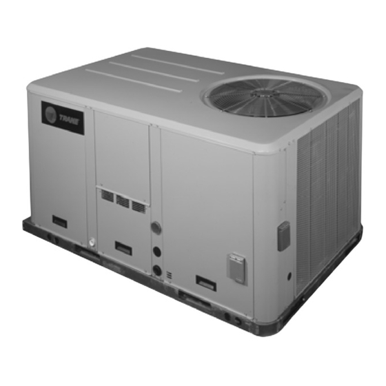
Installation, Operation, and Maintenance Packaged Rooftop Air Conditioners Precedent™ with eFlex™ Technology, Gas/Electric 3 to 10 Tons - 60 Hz Model Numbers: YZC036E YZC072F Model Numbers: YZC048F YZC090F Model Numbers: YZC060E YZC102F Model Numbers: YZC120F SAFETY WARNING Only qualified personnel should install and service the equipment. The installation, starting up, and servicing of heating, ventilating, and air-conditioning equipment can be hazardous and requires specific knowledge and training.
Page 2
PRIOR to Practices servicing the unit. NEVER PERFORM ANY Trane believes that responsible refrigerant practices are SWITCHING, DISCONNECTING, OR VOLTAGE TESTING WITHOUT PROPER ELECTRICAL PPE AND important to the environment, our customers, and the air conditioning industry.
Page 3
Copyright This document and the information in it are the property of Trane, and may not be used or reproduced in whole or in part without written permission. Trane reserves the right to revise this publication at any time, and to make changes to its content without obligation to notify any person of such revision or change.
Model Number Description Digit 1 - Unit Type Digit 14 - Fresh Air Selection Digit 19 - Disconnect/Circuit Breaker (three-phase only) DX Cooling No Fresh Air DX Cooling, Gas Heat Economizer, Dry Bulb 0-100% No Disconnect/No Circuit Breaker without Barometric Relief Unit Mounted Non-Fused...
Model Number Description 12. Epoxy coil and epoxy with hail Digit 27 - Unit Hardware guard option not available for Enhancements units with microchannel No Enhancements Stainless Steel Drain Pan condenser coil. Digit 31 - Advanced Unit Controls 13. Requires selection of 2-inch Standard Unit Controls pleated filters (option B or C) for Human Interface...
General Information Unit Inspection Compressor Nameplate The nameplate for the compressors are located on the side As soon as the unit arrives at the job site of the compressor. Variable speed compressors are not • Verify that the nameplate data matches the data on the marked with a RLA.
Page 9
General Information approximately 0.8' wc and open when the Duct Mounted Relative Humidity Sensor differential falls to 0.7-inch wc. (BAYSENS037*) Compressor Disable (CPR1/2) Field installed, duct mounted humidity sensor is used to control activation of enhanced dehumidification and the This input incorporates the low pressure control (LPC) of hot gas reheat dehumidification options.
General Information sheet metal duct. Each kit contains two sensors. The return The power supply circuit is not balanced with the • air duct sensor (X1310004001) is set to open at 135ºF. The proper phase sequence of L1, L2, L3 for the 3 supply air duct sensor (X1310004002) is set to open at conductors of a 3 phase circuit.
Page 11
Follow the instructions provided below to assure that the and timed override with override cancellation. It is used airflow through the unit is sufficient for adequate with a Trane Integrated Comfort™ building management sampling. Failure to follow these instructions will prevent system.
Page 12
General Information System Input Devices and Functions The RTRM must have a zone sensor or thermostat input in order to operate the unit. The flexibility of having several mode capabilities depends upon the type of zone sensor or thermostat selected to interface with the RTRM. The descriptions of the following basic Input Devices used within the RTRM network are to acquaint the operator with their function as they interface with the various modules.
Pre-Installation WARNING Fiberglass Wool! Exposition to glass wool fibers without all necessary PPE equipment could result in cancer, respiratory, skin or eye irritation, which could result in death or serious injury. Disturbing the insulation in this product during installation, maintenance or repair will expose you to airborne particles of glass wool fibers and ceramic fibers known to the state of California to cause cancer through inhalation.
Dimensions and Weights Unit Clearances necessary to assure adequate serviceability, cataloged unit capacity, and peak operating efficiency. Figure 1, p. 14 illustrates the minimum operating and Providing less than the recommended clearances may service clearances for either a single or multiple unit result in condenser coil starvation, “short-circuiting”...
Page 15
Dimensions and Weights Figure 2. Corner weights WARNING Center of Gravity Length Heavy Objects! Failure to follow instructions below or properly lift unit Center of could result in unit dropping and possibly crushing Gravity operator/technician which could result in death or Width serious injury, and equipment or property-only damage.
Page 16
Dimensions and Weights (a),(b) Table 2. Factory installed options (fiops)/accessory net weights (lbs) T/YZC036E T/YZC048F-060E T/YZC072F T/YZC090-102F T/YZC120F Net Weight Net Weight Net Weight Net Weight Net Weight Accessory 3 Tons 4 to 5 Tons 6 Tons 7.5 to 8.5 Tons 10 Tons Barometric Relief Coil Guards...
Page 17
Dimensions and Weights Figure 6. Cooling and gas/electric - 3 tons - horizontal Figure 9. Cooling and gas/electric - 3 tons ultra high airflow supply/return efficiency - downflow duct connections - field fabricated 3 3/16” 14 1/16” 81 MM (357 MM) 24 3/8”...
Page 18
Dimensions and Weights Figure 11. Cooling and gas/electric - 3 tons ultra high Figure 14. Cooling and gas/electric - 4 to 5 tons ultra efficiency- economizer and barometric relief high efficiency damper hood Top Panel Condenser Fan Evaporator Section Access Panel 40 7/8”...
Page 19
Dimensions and Weights Figure 17. Cooling and gas/electric - 4 to 5 tons ultra Figure 19. Cooling and gas/electric - 4 to 5 tons ultra high efficiency- unit clearance and roof high efficiency- downflow duct connections (a),(b) opening field fabricated Note: All dimensions are in inches/millimeters.
Page 20
Dimensions and Weights Figure 21. Cooling and gas/electric - 4 to 5 tons ultra Figure 24. Cooling and gas/electric - 6 to 10 tons ultra high efficiency- swing diameter for hinged high efficiency - horizontal airflow supply and door(s) option return Note: All dimensions are in inches/millimeters.
Page 21
Dimensions and Weights Figure 27. Cooling and gas/electric - 6 to 10 tons ultra Figure 29. Cooling and gas/electric - 6 to 8.5 tons ultra high efficiency - duct connections field high efficiency - swing diameter for hinged fabricated door(s) option Note: All dimensions are in inches/millimeters.
Page 22
Dimensions and Weights Figure 31. Gas/electric - 6 to 10 tons ultra high efficiency Figure 34. Cooling and gas/electric - 10 tons ultra high - height of gas pipe required from inside of efficiency - unit clearance and roof opening base of unit to gas shut-off assembly (factory Note: All dimensions are in inches/millimeters.
Page 23
Dimensions and Weights Figure 37. Cooling and gas/electric - 10 tons ultra high efficiency - swing diameter for hinged door(s) option Note: All dimensions are in inches/millimeters. Applicable to Y_C models only 17 13/16” 451 MM 22 1/2” 22” 572 MM 559 MM RT-SVX46G-EN...
Installation Foundation Figure 39. 4, 5 tons ultra high efficiency - horizontal supply and return air openings Horizontal Units 3 7/8” 98 MM If the unit is installed at ground level, elevate it above the snow line. Provide concrete footings at each support 9 3/8”...
Installation Note: To assure proper condensate flow during operation, as well as proper operation of the WARNING condensate overflow switch (if equipped), the unit Improper Unit Lift! and curb must be level. Failure to properly lift unit could result in unit dropping If the unit is elevated, a field constructed catwalk around and possibly crushing operator/technician which could the unit is strongly recommended to provide easy access...
Installation • If applicable, assemble and install the roof curb. Refer Table 3. TCO1 tripping values (continued) to the latest edition of the curb installers guide that TCO1 Tripping Values - ships with each curb kit. Unit Model Downflow/ Horizontal TCO Location •...
Installation TCO-1 Instructions for Low NOx Secure the outward edge of each duct cover with 2 screws. Gas Furnace Option 4. For the 4 and 5 ton units, slide RETURN DUCT COVER (insulation side up) into supply opening until inward For units equipped with the low NOx gas furnace option, edge of duct cover engages with the 2 retaining clips the TCO1 is located behind the indoor fan access panel...
Installation Failure to use recommended sealant could Important: Figure 51. For YZC072F-120F result in unit performance loss. If a unit is to be converted to a Horizontal discharge, the Downflow application following conversion must be performed: 1. Remove RETURN and SUPPLY duct covers. 2.
Installation Figure 53. Downflow view Figure 55. Horizontal view 2 Remove 3 Screws 4 Screws Downflow View 3. Lift the tube and bracket from the downflow duct opening. Rotate the tube and bracket assembly 180° ensuring that the holes on the copper sensing tube face away from the unit and face the return air ductwork.
Installation Figure 56. Wireless communication interface - WARNING downflow Proper Field Wiring and Grounding Required! Failure to follow code could result in death or serious injury. All field wiring MUST be performed by qualified personnel. Improperly installed and grounded field wiring poses FIRE and ELECTROCUTION hazards.
Installation Figure 58. Typical through-the-base gas installation 6 1/2” (165 MM) Pipe Nipple 90° Elbow Gas Shut-Off Valve and Street Elbow 90° Elbow and Nipples 5” (127 MM) Pipe Nipple and Union Requirements for Gas Heat • Minimum gas supply pressure for modulating "V" models should be 5.5-inch wc.
Installation Ultra Low NOx Gas Furnace Option - Component Layout Figure 60. NOx gas burner component layout Flame sensor (shown for 90k furnace) Flame rollout switch Inducer motor burner box Pressure switch E box 24V for gas valve Low temperature ambient cutoff switch Field connection...
Installation 2. Remove the support panel that the condensate drain Note: When reversing the drain pan, on some units, the pan exits through. condensate overflow switch will need to be moved to the second hole in its bracket to avoid contact 3.
Installation Main Unit Power the building entering the electrical enclosures. Also seal around conduit and wiring at all roof and curb penetrations. WARNING Figure 62. 3 to 8.5 ton ultra high efficiency units Proper Field Wiring and Grounding Required! Failure to follow code could result in death or serious injury.
Installation Figure 63. ReliaTel™ options module WARNING SPC PRESS DB SPC PRESS Hazardous Voltage! DA HEAT Failure to disconnect power before servicing could DA COOL result in death or serious injury. Disconnect all electric FAN SPD power, including remote disconnects before servicing. Follow proper lockout/tagout procedures to ensure the power can not be inadvertently energized.
Installation Figure 65. ReliaTel™ control customer low voltage routing (all units) Communication Refrigeration Communication Refrigeration Interface Module Interface Module Unpowered Convenience Outlet ReliaTel Conventional Wiring ReliaTel Route Field Wiring as shown TBU Wiring Secure Field and Secure with 2 Wire Ties Route Field Wiring as shown Installed Wiring and Secure with 3 Wire Ties...
Page 39
Installation Table 6. Temperature vs. resistance Table 8. Iron pipe size (SI) millimeters Temperature Iron Pipe Size (SI) Millimeters Nominal Resistance Length of Pipe Degrees F° Degrees C° 15 mm 20 mm 25 mm 32 mm 40 mm (Meters) -20° -28.9°...
Pre-Start Use the checklist provided below in conjunction with the and record the voltage between phases 1, 2, and 3 and “General Unit Requirements” checklist to ensure that the calculate the amount of imbalance as follows: unit is properly installed and ready for operation. 100 x AV - VD % Voltage Imbalance= where;...
Pre-Start Note: Upon closing main power disconnect and the unit Note: Upon closing main power disconnect and the unit mounted disconnect switch or circuit breaker, the mounted disconnect switch or circuit breaker, the phase monitor will verify proper phasing. If LED on phase monitor will verify proper phasing.
Unit Startup Verifying Proper Air Flow “Default Operation” section above with the exception of the supply fan speed when the unit has an active cooling demand and the economizer is enthalpy enabled. WARNING Heating Operation Live Electrical Components! During staged heating operation, the control will monitor the space temperature and space heating setpoint and Failure to follow all electrical safety precautions when with a PI control algorithm determine if active heating...
Unit Startup While economizing, the mechanical cooling is disabled If the system control is local, the DWU initiation setpoint is until the economizer dampers have been fully open for 3°F below the morning warm-up setpoint. The termination three minutes. If the economizer is disabled due to setpoint is equal to the morning warm-up setpoint.
Unit Startup from previous component startup or until the desired ReliaTel™ Control: Follow the Test Guide in Table 9, startup component test is started. p. 42 to start the unit in the heating mode. Momentarily jump across the Test 1 and Test 2 terminals on LTB1 one 1.
Page 46
Unit Startup • Program the Night Setback (NSB) panel (if applicable) for proper unoccupied operation. Refer to the programming instructions for the specific panel. • Verify that the Remote panel “System” selection switch, “Fan” selection switch, and “Zone Temperature” settings for automatic operation are correct.
Maintenance Airflow through the unit is affected by the amount of dirt and debris accumulated on the indoor coil and filters. To WARNING insure that airflow through the unit is adequate for proper Hazardous Service Procedures! sampling by the return air smoke detector, complete adherence to the maintenance procedures, including Failure to follow all precautions in this manual and on the tags, stickers, and labels could result in death or...
Maintenance • Record this data on an “operator’s maintenance log” Microchannel (MCHE) Coils like the one shown in Table 10, p. 49. If the operating pressures indicate a refrigerant shortage, measure the NOTICE system superheat. For guidelines, refer to the “Compressor Startup”...
Maintenance 2. Protect all electrical devices such as motors and 11. Restore the unit to its operational status and check controllers from any over spray. system operation. 3. Straighten any bent coil fins with a fin comb. Annual Maintenance WARNING •...
Troubleshooting • System status WARNING • Heating status Hazardous Service Procedures! • Cooling status Failure to follow all precautions in this manual and on If a system failure is indicated, proceed to Step 5. If no the tags, stickers, and labels could result in death or failures are indicated, proceed to Step serious injury....
Troubleshooting Service Failure Zone Sensor LED 3 (Cool) “On” when the cooling cycle is operating. • If the supply fan proving switch has closed, the unit will not operate (when connected to RTOM), check the fan “Off” when the cooling cycle terminates or the LED fails. motor, belts, and proving switch.
Troubleshooting Fan Failure Switch each respective terminal wire (6 through 10) from the Zone Sensor to the unit J6 terminals 6 through 10. When the “Fan Failure” switch is wired to the RTOM, the Note: If the system is equipped with a programmable LED will remain flashing the entire time the fan proving zone sensor, BAYSENS119* the LED indicators will switch is closed, indicating a fan failure, and it will shut the...
Troubleshooting Test 4 - LED Indicator Test, (SYS ON, 4. Verify all modes of operation, by running the unit through all of the steps in the “Test Modes” section HEAT, COOL and SERVICE) discussed in “Unit Startup”. Method 1. Testing the LED using a meter with diode test 5.
Troubleshooting Table 12. Fault detection and diagnostic codes Primary Fault Codes Information Code Temp Mixed Air Outdoor Pressure Space Unit Economizer RTEM Sensor Airflow Unit Fails Damper Temp Temp Dead band Press Dead Economizing Failures Actuator Comm Fail Sensor Fail Position % Sensor Sensor...
Unit Wiring Diagrams Numbers Note: Wiring diagrams can be accessed using e-Library order number search field or by contacting by entering the diagram number in the literature technical support. Table 14. Unit wiring diagram numbers Schematic Type Drawing Number Description 230,460,575V 1213-1929 Diagram Controls;...
Models Less Than 20 Tons for Commercial Trane Use* 2701 Wilma Rudolph Blvd. This warranty is extended by Trane to the original Clarksville, TN 37040-1008 purchaser and to any succeeding owner of the real Attention: Manager, Product Service property to which the Combination Gas Electric Air...
Page 60
For more information, please visit trane.com or americanstandardair.com. Trane and American Standard have a policy of continuous product and product data improvement and reserve the right to change design and specifications without notice. We are committed to using environmentally conscious print practices.
Need help?
Do you have a question about the Precedent YZC036E and is the answer not in the manual?
Questions and answers