Table of Contents
Advertisement
Available languages
Available languages
Quick Links
IMPORTANT! Read all instructions before installing and using. Installer: This manual must be delivered to the end user.
WARNING!
Failure to install or use this product according to manufacturer's recommendations may result in property damage, serious injury, and/
or death to those you are seeking to protect!
Do not install and/or operate this safety product unless you have read and understood the safety information
contained in this manual.
1.
Proper installation combined with operator training in the use, care, and maintenance of emergency warning devices are essential to
ensure the safety of emergency personnel and the public.
2.
Emergency warning devices often require high electrical voltages and/or currents. Exercise caution when working with live electrical
connections.
3.
This product must be properly grounded. Inadequate grounding and/or shorting of electrical connections can cause high current arcing,
which can cause personal injury and/or severe vehicle damage, including fire.
4.
Proper placement and installation is vital to the performance of this warning device. Install this product so that output performance of
the system is maximized and the controls are placed within convenient reach of the operator so that they can operate the system without
losing eye contact with the roadway.
5.
Do not install this product or route any wires in the deployment area of an air bag. Equipment mounted or located in an air bag
deployment area may reduce the effectiveness of the air bag or become a projectile that could cause serious personal injury or death.
Refer to the vehicle owner's manual for the air bag deployment area. It is the responsibility of the user/operator to determine a suitable
mounting location ensuring the safety of all passengers inside the vehicle particularly avoiding areas of potential head impact.
6.
It is the responsibility of the vehicle operator to ensure daily that all features of this product work correctly. In use, the vehicle operator
should ensure the projection of the warning signal is not blocked by vehicle components (i.e., open trunks or compartment doors),
people, vehicles or other obstructions.
7.
The use of this or any other warning device does not ensure all drivers can or will observe or react to an emergency warning signal.
Never take the right-of-way for granted. It is the vehicle operator's responsibility to be sure they can proceed safely before entering an
intersection, drive against traffic, respond at a high rate of speed, or walk on or around traffic lanes.
8.
This equipment is intended for use by authorized personnel only. The user is responsible for understanding and obeying all laws
regarding emergency warning devices. Therefore, the user should check all applicable city, state, and federal laws and regulations. The
manufacturer assumes no liability for any loss resulting from the use of this warning device.
Size:
CD5051VDL1
CD5051VDL2
Weight:
CD5051VDL1
CD5051VDL2
Input Voltage:
Current (Max):
CD5051VDL1
CD5051VDL2
Power (Max):
CD5051VDL1
CD5051VDL2
Temp. Range:
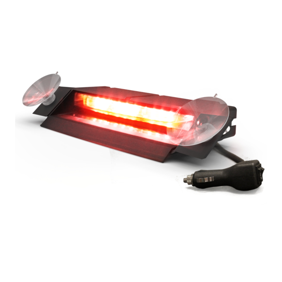
Installation and Operation Instructions
CD5051VDL Series Deck, Dash & Visor
FOR INTERIOR USE ONLY
Light head only: 5.88 W x 1.56 D x 0.75" H
Light head with shroud: 6.5" W x 2.88" D x 1.0" H
Light head only: 11.4" W x 1.6" D x 0.75" H
Light head with shroud: 12.1" W x 3.0" D x 1.0" H
0.95 lbs.
1.7 lbs.
12-24 VDC
0.86 A @ 12 VDC
1.7 A @ 12 VDC
11.0 W @ 12 VDC
21.1 W @ 12 VDC
-40ºC to 65ºC
-40ºF to 149ºF
Light
Page 1 of 7
Advertisement
Table of Contents

Related Manuals for Code 3 CD5051VDL1 Series


Summary of Contents for Code 3 CD5051VDL1 Series
- Page 1 Installation and Operation Instructions CD5051VDL Series Deck, Dash & Visor Light FOR INTERIOR USE ONLY IMPORTANT! Read all instructions before installing and using. Installer: This manual must be delivered to the end user. WARNING! Failure to install or use this product according to manufacturer’s recommendations may result in property damage, serious injury, and/ or death to those you are seeking to protect! Do not install and/or operate this safety product unless you have read and understood the safety information contained in this manual.
-
Page 2: Installation And Mounting
Installation & Mounting: Note: Image shown is a CD5051VDL2 product. Use the same installation & mounting instructions for CD5051VDL1 product series. Carefully remove the unit from its packaging. Examine the unit for transit damage. If damage is found, return the product to your local dealer for warranty replacement. -
Page 3: Top View
TOP VIEW SIDE VIEW Figure 4 Figure 5 Standard Mounting without Shroud: Figure 6 Figure 7 Mounting with VHB Tape: Mounting with Suction Cup: 1. Carefully remove the light head from the shroud. 1. Carefully remove the light head from the shroud. CAUTION: gently release the locking tabs to avoid breaking the tabs CAUTION: gently release the locking tabs to avoid breaking the tabs shown in Figure A . - Page 4 Synchronization: The CD5051VDL series is capable of syncing with other compatible CODE 3 products by following these steps: 1.Set the desired flash pattern on each unit individually. It is also strongly recommended that the same style of flash pattern be used on all units to produce the most effective warning pattern.
- Page 5 FLASH PATTERN SELECTION (CIGARETTE ADAPTER): ON - COLOR 2 PATTERN SELECT ON - COLOR 1 CD5051VDL1 Series Flash Pattern Chart/CD5051VDL1 Serie Tabla de patrones de destello CD5051VDL1 Série Tableau des effets clignotants/CD5051VLD1 Serie Blitzmusterdiagramm SAE J595 CA T13 LED Color 1 & Color LED Color 2 &...
- Page 6 CD5051VDL2 Series Flash Pa�ern Chart/CD5051VDL2 Serie Tabla de patrones de destello/ CD5051VDL2 Série Tableau des effets clignotants/CD5051VLD2 Serie Blitzmusterdiagramm SAE J595 CA Title 13 Pa�ern Mode Descrip�on Phase RW, BW, AW RWBW RW, BW, AW RWBW Single Flash - Simultaneous Color 1 Class 1 Class B Single Flash - Simultaneous Color 1...
- Page 7 Truganina Victoria, Australia Seacroft, Leeds, England LS14 1FB (314) 996-2800 +61 (0)3 8336 0680 +44 (0)113 2375340 c3_tech_support@code3esg.com esgapsales@eccogroup.com esguk-code3@eccogroup.com CODE3ESG.com CODE3ESG.com/au/en CODE3ESG.co.uk An ECCO SAFETY GROUP™ Brand ECCOSAFETYGROUP.com © 2020 CODE 3 920-0839-01 Rev. E Page 7 of 7...
- Page 8 Instrucciones de instalación y operación Luz de cubierta, tablero y visor de la serie CD5051VDL SOLO PARA USO INTERIOR ¡IMPORTANTE! Lea todas las instrucciones antes de instalar y utilizar. Instalador: Este manual se debe entregar al usuario final. ¡ADVERTENCIA! Si no sigue las instrucciones del fabricante a la hora de instalar o usar el producto, pueden producirse daños materiales, y lesiones graves o incluso mortales a aquellos que pretende proteger! No instale ni opere este producto de seguridad, a menos que haya leído y comprendido la información de seguridad contenida en este manual.
-
Page 9: Instalación Y Montaje
Instalación y montaje: Nota: La imagen que se muestra es un producto CD5051VDL2. Utilice las mismas instrucciones de instalación y montaje para la serie de productos CD5051VDL1. Retire cuidadosamente la unidad de su embalaje. Examinar la unidad en busca de daños producidos durante el transporte. Si se detectan daños, devuelva el producto a nuestro distribuidor local para obtener un reemplazo de garantía. - Page 10 VISTA VISTA SUPERIOR LATERAL Figura 4 Figura 5 Montaje estándar sin cubierta: Figura 6 Figura 7 MONTAJE CON CINTA DE ADHERENCIA MUY ALTA: MONTAJE CON VENTOSA: 1. Retire con cuidado el cabezal de luz de la cubierta. 1. Retire con cuidado el cabezal de luz de la cubierta. PRECAUCIÓN: Suelte suavemente las pestañas de bloqueo para evitar PRECAUCIÓN: Suelte suavemente las pestañas de bloqueo para evitar que se rompan las pestañas que se muestran en la Figure A .
-
Page 11: Instrucciones De Cableado
Conecte el cable azul al cable de alimentación rojo. Sincronización: La serie CD5051VDL es capaz de sincronizarse con otros productos CODE 3 compatibles siguiendo estos pasos: 1. Ajuste el patrón de destello deseado en cada unidad de manera individual. También se recomienda encarecidamente que se utilice el mismo estilo de patrón de destello en todas las unidades para producir el patrón de advertencia más efectivo. - Page 12 Selección de patrón de parpadeo (Adaptador de cigarrillos): ENCENDIDO - COLOR 2 SELECCIONAR PATRÓN APAGADO ENCENDIDO - COLOR 1 Página 5 de 6...
- Page 13 Algunas jurisdicciones no permiten la exclusión ni la limitación de daños incidentales o consecuenciales. 10986 North Warson Road, St. Louis, MO 63114 USA Sevicio Técnico USA (314) 996-2800 c3_tech_support@code3esg.com CODE3ESG.com An ECCO SAFETY GROUP™ Brand ECCOSAFETYGROUP.com © 2020 CODE 3 920-0839-01 Rev. E Página 6 de 6...
-
Page 14: Instructions D'installation Et D'utilisation
Instructions d'installation et d'utilisation Éclairage de pont, de tableau de bord et de pare-soleil de la série CD5051 VDL POUR UN USAGE INTÉRIEUR UNIQUEMENT IMPORTANT! Lisez toutes les instructions avant d’installer et d’utiliser le produit. Installateur : ce manuel doit être remis à l’utilisateur final. AVERTISSEMENT! Lisez toutes les instructions avant d’installer et d’utiliser le produit. -
Page 15: Installation Et Montage
Installation et montage: Remarque: l’image présentée est un produit CD5051VDL2. Utilisez les mêmes instructions d’installation et de montage pour la série de produits CD5051VDL1. Retirer délicatement l’appareil de son emballage. Vérifier que l’appareil n’a pas été endommagé pendant le transport. En cas de dommage, renvoyer le produit à... -
Page 16: Vue Latérale
Vue de dessus Vue latérale Figure 4 Figure 5 Montage standard sans déflecteur: Figure 6 Figure 7 MONTAGE AVEC RUBAN ADHÉSIF VHB: MONTAGE AVEC VENTOUSE: 1. Retirer avec précaution la tête d’éclairage du déflecteur. 1. Retirer avec précaution la tête d’éclairage du déflecteur. ATTENTION : relâcher doucement les languettes de verrouillage pour ATTENTION : relâcher doucement les languettes de verrouillage pour éviter de les casser comme illustré... - Page 17 Connecter le fil bleu au fil d’alimentation rouge. Synchronisation: La série CD5051VDL est capable de se synchroniser avec d’autres produits CODE 3 compatibles en suivant ces étapes: 1.Régler le schéma de clignotement souhaité sur chaque unité individuellement. Il est aussi fortement recommandé d’utiliser le même style d’effet de clignotement sur toutes les unités pour produire l’avertissement le plus efficace.
- Page 18 Sélection du modèle de clignotement(ADAPTATEUR CIGARETTE): ON - COULEUR 2 SÉLECTION DE MODÈLE ON - COULEUR 1 Page 5 sur 6...
- Page 19 à l’autre. Certaines juridictions ne permettent pas l’exclusion ou la limitation des dommages indirects ou consécutifs. 10986 North Warson Road, St. Louis, MO 63114 USA Service Technique USA (314) 996-2800 c3_tech_support@code3esg.com CODE3ESG.com An ECCO SAFETY GROUP™ Brand ECCOSAFETYGROUP.com © 2020 CODE 3 920-0839-01 Rev. E Page 6 sur 6...
-
Page 20: Installations- Und Bedienungsanleitung
Installations- und Bedienungsanleitung Leuchte der Serie CD5051VDL zum Anbringen an Verdeck, Armaturenbrett und Sonnenblende NUR FÜR DEN INNENBEREICH WICHTIG! Lesen Sie vor der Installation und Verwendung alle Anweisungen. Monteur: Diese Anleitung muss dem Endbenutzer zugestellt werden. WARNUNG! Wenn Sie dieses Produkt nicht gemäß den Empfehlungen des Herstellers installieren oder verwenden, kann dies zu Sachschäden, schweren Personenschäden und/oder zum Tod für Sie und die Personen, denen Sie helfen möchten, führen! Installieren und/oder verwenden Sie dieses Sicherheitsprodukt nur, wenn Sie die Sicherheitsinformationen in dieser Anleitung gelesen und verstanden haben. - Page 21 Installation et montage: HINWEIS: Das gezeigte Bild ist ein CD5051VDL2-Produkt. Verwenden Sie für die Produktreihe CD5051VDL1 die gleichen Installations- und Montageanweisungen. Nehmen Sie das Produkt vorsichtig aus der Verpackung. Überprüfen Sie das Produkt auf Transportschäden. Wenn Schäden festgestellt werden, senden Sie das Produkt an unseren lokalen Händler, um es im Rahmen der Garantie auszutauschen. Verwenden Sie keine beschädigten Teile.
- Page 22 Ansicht von Ansicht von oben der Seite Abbildung 4 Abbildung 5 Standardmontage ohne Einfassung: Abbildung 6 Abbildung 7 BEFESTIGUNG MIT KLEBEBAND MIT HOHER HAFTUNG: MONTAGE MIT SAUGNAPF: 1. Entfernen Sie vorsichtig den Leuchtenkopf von der Einfassung. 1. Entfernen Sie vorsichtig den Leuchtenkopf von der Einfassung. ACHTUNG: Lösen Sie vorsichtig die Verriegelungslaschen, um zu ACHTUNG: Lösen Sie vorsichtig die Verriegelungslaschen, um zu vermeiden, dass die in Abb.
- Page 23 Verbinden Sie das blaue Kabel mit dem roten Stromkabel. Synchronisierung: Die CD5051VDL-Serie kann mithilfe der folgenden Schritte mit anderen kompatiblen CODE 3-Produkten synchronisiert werden: 1.Stellen Sie das gewünschte Leuchtmuster für jedes Gerät einzeln ein. Es wird außerdem dringend empfohlen, für alle Geräte dasselbe Leuchtmuster zu verwenden, um ein effektives Warnmuster zu erzeugen.
- Page 24 Auswahl des Leuchtmusters(ZIGARETTENADAPTER): EIN - FARBE 2 MUSTER AUSWÄHLEN EIN - FARBE 1 Seite 5 von 6...
- Page 25 10986 North Warson Road Riedweg 58-60, St. Louis, MO 63114 USA Ulm, 89081, Germany (314) 996-2800 +49 731 935 210 c3_tech_support@code3esg.com ulm@eccogroup.com CODE3ESG.com CODE3ESG.co.uk An ECCO SAFETY GROUP™ Brand ECCOSAFETYGROUP.com © 2020 CODE 3 920-0839-01 Rev. E Seite 6 von 6...
Need help?
Do you have a question about the CD5051VDL1 Series and is the answer not in the manual?
Questions and answers