Table of Contents
Advertisement
Quick Links
Advertisement
Table of Contents

Related Manuals for Gemini Tinytag TGE-0001


Summary of Contents for Gemini Tinytag TGE-0001
-
Page 2: Table Of Contents
Contents Contents Warnings and PAT Testing Instructions Introduction In the Case Controls and Connections Logger Display Logger Markings Quick Start Modes of Operation: Single Phase Current Three Phase Current Single Phase Current and Voltage Three Phase Current and Voltage 12.1 Positioning Coils 12.2 Screen Messages 12.3 Manual Configuration Data Logging... -
Page 3: Warnings And Pat Testing Instructions
• Keep away from pacemakers • The current measurement inputs must only be connected to approved flexible coil current transducers, Gemini part • Keep away from iPods and hard drives number ACS-002X. Any other type of connection may damage the logger and expose the user to hazardous •... -
Page 4: Introduction
Introduction In the Case The Tinytag Energy logger combines the level of performance required by experts with the level of simplicity required by those that are new to energy management. The logger is ideal for monitoring building energy supply, sections within a building or individual pieces of equipment. Data from the Tinytag Energy Logger can be used to identify power-hungry or inefficient equipment and peak load times, and can highlight equipment that is left powered up or idling... -
Page 5: Controls And Connections
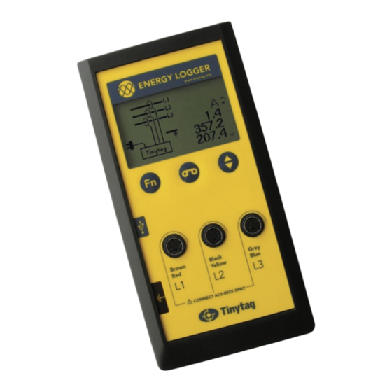
Controls and Connections Logger Display 1. Wiring Configuration This shows the different wiring configurations supported by the logger. To step though them, press the Function button. 2. Prompts and Error Messages When a wiring configuration is selected, the logger will show prompts in this area of the display to tell the user what needs to be plugged in next. -
Page 6: Logger Markings
MAgnET available, in line with local regulations. This product is fitted with a strong magnet In accordance with the WEEE directive Gemini to attach the unit to panels whilst in use. This Data Loggers (UK) Ltd. will take back and symbol on the back of the logger indicates dispose of any equipment purchased directly. -
Page 7: Quick Start
Quick Start Starting an Energy Logger Insert the supplied batteries in logger, observing the correct polarity. Press any of the loggers three buttons to wake it up. Select the wiring configuration to be monitored by pressing the function button. Follow the on-screen prompts and plug in the current coils and mains lead as directed. -
Page 8: Modes Of Operation
Modes of Operation: Modes of Operation: Single Phase Current Three Phase Current Set-up Set-up For monitoring single-phase current where no mains For monitoring three-phase current where no mains connection is available. connection is available. In this mode the logger will be powered by its batteries, and In this mode the logger will be powered by its batteries, and will be able to log for a minimum of two months. -
Page 9: Single Phase Current And Voltage
Modes of Operation: Modes of Operation: Single Phase Current and Voltage Three Phase Current and Voltage Set-up Set-up For monitoring single-phase current with a voltage reference. For monitoring three-phase current with a voltage reference. In this mode the logger will be powered from the mains, and In this mode the logger will be powered from the mains, and will be able to log for six weeks before it fills its memory at will be able to log for six weeks before it fills its memory at... -
Page 10: Positioning Coils
Modes of Operation: 12.1 Modes of operation: Three Phase Current and Voltage Three Phase Current and Voltage (cont.) Set-up Positioning Coils (cont.) • Clip the coils around the correct conductors. For Automatic Configuration recommendations on coil positioning, see page 20. Before logging can be started the logger has to determine •... - Page 11 12.1 Modes of operation: Three Phase Current and Voltage Positioning Coils Care should be taken when positioning coils during the set up of the logger to ensure they are well spaced, don’t overlap or are placed too closely to neighbouring conductors.
-
Page 12: Screen Messages
12.2 Modes of operation: Three Phase Current and Voltage Screen Messages Plug in I1, I2, or I3 This error messages indicate that one or more coils are Battery Low not connected to the logger. The batteries in the logger need replacing. Proximity I1 and I2 Checking Coils... -
Page 13: Manual Configuration
12.3 Modes of operation: Three Phase Current and Voltage Manual Configuration In some applications, such as those where conductors are armoured, the logger may fail to configure automatically. In these instances, it may still be possible to get it to configure. Phase Matching Diagram This is a tool that may help to visualise the separation of coils that are too close to each other. -
Page 14: Data Logging
12.3 Modes of operation: Data Logging Three Phase Current and Voltage (cont.) Data Logging The mains connection and relative order information is shown The energy logger can be started and stopped multiple on the left-hand side of the screen, whilst the readings from times without needing to connect it to a computer. -
Page 15: Tinytag Explorer
Tinytag Explorer Tinytag Explorer Starting Tinytag Explorer The Tinytag Explorer software is used to reconfigure an To start Tinytag Explorer, click on the desktop icon energy logger and to view recorded data. for the software: The following takes you through the process of installing If you didn’t create a desktop icon when installing the Tinytag Explorer, the basics of configuring an energy logger software, you can start the software by going to:... - Page 16 Tinytag Explorer (cont.) offloading Data Old data files are shown fainter than ones that have not been downloaded before. Because the energy logger can be used to record multiple Viewing Data runs, it displays multiple files, one for each recording session, so the user can chose what data they wish to view.
- Page 17 Tinytag Explorer (cont.) Logging Interval Configuring an Energy Logger To configure an energy logger, to change how often a unit records, or to clear old readings from a unit, click the Configure icon: The Logging Interval option enables you to set how often an energy logger will record (the minimum interval is 30 seconds).
-
Page 18: What Does The Logger Record
What Does the Logger Record? Display The logger’s display shows instantaneous RMS current (A) from all three phases, the instantaneous RMS voltage (V), an instantaneous overall power figure (kW) and power factor information for all three phases. Automatic Software Calculations When data is downloaded in the Tinytag Explorer software, the following information is calculated and displayed: •... -
Page 19: How The Energy Logger Works
how the Energy Logger Works Voltage Average and Peak Mains voltage is measured by direct connection to the mains The 100ms burst of readings is repeated every two seconds supply. The data logger samples the voltage signal at 1kHz (this is reduced to every five seconds if logging on batteries, for 100ms to calculate RMS voltage and true power. -
Page 20: Logging Specification
Logging Specification Measurement Specification Logging Interval 30 seconds to Range 10 days Current 2,000A AC RMS (Momentary Reading Capacity Six weeks at the peak surge current: 2x rated range) default 5 minute logging interval Voltage 200-253V AC nominal Frequency Nominal 50/60Hz Display Resolution Current 0.1A... -
Page 21: Physical Specification
Physical Specification Maintenance & Service Instructions Logger Maintenance operational Temperature Range 0 to +50°C Energy loggers can be cleaned as follows: Maximum humidity 95% (non-condensing) Remove all leads and cables from the logger. Maximum Altitude 3,000m Wipe the case with a moist cloth using a mild detergent. -
Page 22: Battery Information
Approvals and Warranty Battery Type 4 x 1.5V AA Alkaline Approvals Batteries Gemini Data Loggers (UK) Ltd. operates Quality and Battery Life 60 days, typical, based on a Environmental Management Systems which conform to ISO battery capacity of 2500mAH* 9001 and ISO 14001. - Page 23 Designed and Manufactured by: Gemini Data Loggers (UK) Ltd. Scientific House, Terminus Road, Chichester, West Sussex, PO19 8UJ England. www.tinytag.info +44 (0)1243 813000 sales@tinytag.info...
Need help?
Do you have a question about the Tinytag TGE-0001 and is the answer not in the manual?
Questions and answers