Table of Contents
Advertisement
Quick Links
Advertisement
Table of Contents

Subscribe to Our Youtube Channel
Related Manuals for A.O. Smith AHPM-270


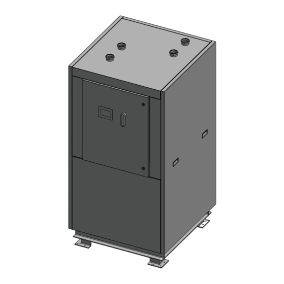
Summary of Contents for A.O. Smith AHPM-270
- Page 1 User’s Information Manual Series 100 Models: AHPM-270 - AHPM- 540 - AHPM-810 - AHPM-1080 - AHPM-1350 - AHPM-1620 - AHPM-1890 - AHPM-2160 Modular Water Source Commercial Heat Pump Water Heating Systems Certified UL 1995:2015 CSA C22.2 NO. 236:2015...
-
Page 3: Table Of Contents
TABLE OF CONTENTS SAFE INSTALLATION, USE AND SERVICE....1 INSTALLATION............14 GENERAL SAFETY INFORMATION......2 REQUIRED ABILITY.............14 PRECAUTIONS..............2 GENERAL.................14 GROUNDING INSTRUCTIONS..........2 REQUIRED TOOLS & MATERIALS........14 INTRODUCTION............3 INSTALLATION & START UP TOOLS......14 QUALIFICATIONS..............3 SERVICE TOOLS..............15 PREPARING FOR THE INSTALLATION........3 UNIT PLACEMENT..............15 PRINCIPLE OF OPERATION..........4 MOUNTING FRAME............15 THE REFRIGERATION CYCLE..........4 PAD MOUNTING.............15... - Page 4 TABLE OF CONTENTS SINGLE UNIT HOME SCREEN OPERATING WITH MASTER CONTROLS.......23 SINGLE UNIT HOME SCREEN OPERATING AS A SINGLE UNIT ( IN DEFROST)....23 SINGLE UNIT HOME SCREEN DISPLAYING ALARM STATUS..........23 SINGLE UNIT ALARM SCREEN.........23 SINGLE UNIT PIPE CONFIGURATION SCREEN.....23 SINGLE UNIT TANK CONFIGURATION SCREEN....23 SINGLE UNIT IP ADDRESS CONFIGURATION....23 SINGLE UNIT HEAT BANK SCREEN........23 MEMBER SCREEN TERMINOLOGY......24...
-
Page 5: Safe Installation, Use And Service
SAFE INSTALLATION, USE AND SERVICE The proper installation, use and servicing of this commercial heat pump water heater is extremely important to your safety and the safety of others. Many safety-related messages and instructions have been provided in this manual and on your own heat pump water heater to warn you and others of a potential injury hazard. -
Page 6: General Safety Information
GENERAL SAFETY INFORMATION PRECAUTIONS GROUNDING INSTRUCTIONS This heat pump water heater must be grounded in accordance **DO NOT USE THIS UNIT IF ANY PART HAS BEEN UNDER WATER.** with the National Electrical Code and/or local codes. These Immediately call a qualifi ed service agency to inspect the unit must be followed in all cases. -
Page 7: Introduction
INTRODUCTION Thank you for purchasing this heat pump water heater. Properly This manual contains instructions for the installation, operation, installed and maintained, it should give you years of trouble and maintenance of the heat pump water heater (HPWH). It free service. also contains warnings throughout the manual that you must read and be aware of. -
Page 8: Principle Of Operation
4. In order to expedite your request, please have full model liquid refrigerant the evaporator is unable to vaporize during and serial number available for the technician. low temperature operating conditions. The accumulator prevents liquid refrigerant from entering the compressor 5. -
Page 9: Features & Components
FEATURES & COMPONENTS PRODUCT ILLUSTRATION Electrical Enclosure Evaporator (Heat Exchanger) (Water to Refrigerant) Condenser (Heat Exchanger) (Refrigerant To Potable Water) Evaporator Flow Switch Hot Water Out Hot Water In Source Water Out Source Water In Compressor Filter Dryer Figure 1 Component Refrigeration Circuit Refrigerant State Component Heated Water Circuit... - Page 10 Condenser Paddle Wheel Flow Sensor Thermostatic Expansion Valve (TXV) Receiver Accumulator...
-
Page 11: Water To Water Cycle
WATER TO WATER CYCLE... -
Page 12: Rough In Dimensions
Flow Rate Heating Outlet Length Width Height Weight Weight (GPM) (GPM) Water (LBS) (LBS) BTUH BTUH (FPT) AHPM-270 277,100 210,000 2” 34 ⅞ ” 36 ¼ ” 68 ½ ” 1,150 1,300 AHPM-540 554,200 414,450 2” 64 ¼ ” 36 ¼ ” 68 ½ ”... -
Page 13: Installation Requirements
INSTALLATION REQUIREMENTS Read all installation requirements in this manual before SOURCE WATER TEMPERATURE installation begins. ENTERING SOURCE WATER TEMPERATURE The installation must conform to these instructions and all The entering source water temperature range of operation for local and national code authority having jurisdiction. the unit is 40°... -
Page 14: Clearances
28.2 Note: Each unit is made of multiple AHPM-270 units. the above data is based on each unit having its own disconnect. the total incoming MCA and MFS are used for the power needed in the building if all units were run off of one disconnect. -
Page 15: Minimum Wire Size
MINIMUM WIRE SIZE Allowable Ampacities of Insulated Conductors Single-phase heat pump water heaters are two wire circuits. Three-phase heaters are three wire circuits. In addition to the foregoing, a grounded conductor is required. Not more than three conductors in raceway, cable, or earth (directly buried), based on ambient temperature of 30°C (86°F) TABLE 3... -
Page 16: Water Piping
Contact a local plumbing service agency to have a Water Connection and Flow thermal expansion tank installed on all closed water systems. Water Flow Rate Connection Size Unit (GPM) (Inches) MIXING VALVES AHPM-270 2” AHPM-540 2” AHPM-810 2” AHPM-1080 2” AHPM-1350 2”... -
Page 17: Contaminated Water
Mixing valves are available at plumbing supply stores. Consult a Qualifi ed Installer or Service Agency. Follow the mixing valve manufacturer’s instructions for installation of the valves. TABLE 5 TANK SELECTION CONTAMINATED WATER The HPWH unit is not an instantaneous water heater and must be connected to a storage tank. -
Page 18: Storage Recommendations
• IMPORTANT: Do not remove, cover or deface any permanent instructions, wiring diagrams, labels, or the rating label from the outside cabinet or the inside panels on the HPWH unit. FIGURE 5 • Do not tilt the unit beyond 45° at any time. All internal components are braced from the base of unit. -
Page 19: Service Tools
Heat transfer compound (paste) such as Honeywell part be evenly dispersed across the footing channels on the bottom number 107408 or equivalent. of the unit. See Table 1 on page 8 for unit dimensions and weights. Electrical switch lock out device - used to secure disconnect switches/breaker panels while servicing. -
Page 20: Water Connections
WATER CONNECTIONS 14. All components in the hot water supply system must be adequately sized to meet peak water fl ow requirement Water piping must be installed in accordance with the instructions 15. When the HPWH unit is installed above the storage tank in this manual and all local plumbing codes having jurisdiction. -
Page 21: Standard Tank Thermostat
Ensure required clearances are maintained and there is access for servicing. See Clearances on page 10. WATER PIPING Ensure the outlet (supply) and inlet (return) water piping connected to the HPWH are not less than the connection size on the unit. See Table 1 on page 8. Ensure swing-type check valves (not spring-loaded types) are installed on outlet lines of all heat pumps plumbed in parallel to prevent hot water short-circuiting. -
Page 22: Pre-Startup Checklist
15. Ensure the power supply wiring meets the MCA (Minimum 3 PHASE STARTUP PROCEDURES Circuit Ampacity) requirements shown in this manual and • Make sure the disconnect is off and confi rm there is no on the HPWH data label. power on the distribution block on the electrical panel. -
Page 23: Initial Start-Up
INITIAL START-UP upon phasing of the power to L1, L2 and L3. Since there is a 50/50 chance of connecting power in such a way as to cause CAUTION OIL DILUTION! Bearing malfunction! It is important rotation in the reverse direction, it is important to include to ensure that new compressors are not subjected to liquid notices and instructions in appropriate locations on the abuse. -
Page 24: Programmable Logic Controls
If the HPWH does not start immediately: start up, mark the valve position and remove the valve handle to ensure it is not accidentally changed. • Wait 5 minutes in case the anti short cycle timer has halted operation. This control system feature protects If the temperature rise through the HPWH is consistently the HPWH from rapid short cycling that can cause greater than 12°F the water fl ow may be restricted. -
Page 25: Setpoints Ranges & Safeties
MASTER PANEL ALARM SCREEN Setpoint Ranges & Safeties Factory Safety Action Setting Low Flow < 4.4 Gal/Min Shutoff (heating /cooling side) Evaporator Temperature 34° F Shutoff Defrost Cut-In Evaporator Temperature 38° F Alarm Defrost Cut-Out Temperature Setpoint 100° F - 160° F Range High Refrigerant Pressure... -
Page 26: Alarm Screen
“Evap1” – Evaporator 1: indicates the evaporator temperature “SAVE”button – Saves the“Tank Diff Set”and“System Timer” of the fi rst evaporator parameters “CTD”– Compressor Time Delay: indicates remaining time in “Master IP Address” – IP Address used to connect panel to compressor delay countdown BMS system “PTD”... -
Page 27: Member Screens
MEMBER SCREENS SINGLE UNIT PIPE CONFIGURATION SCREEN SINGLE UNIT HOME SCREEN OPERATING WITH MASTER CONTROLS SINGLE UNIT TANK CONFIGURATION SCREEN SINGLE UNIT HOME SCREEN OPERATING AS A SINGLE UNIT (IN DEFROST) SINGLE UNIT IP ADDRESS CONFIGURATION SCREEN (FOR USE CONTACT AO SMITH) SINGLE UNIT HOME SCREEN DISPLAYING ALARM SINGLE UNIT HEAT BANK SCREEN SINGLE UNIT ALARM SCREEN... -
Page 28: Member Screen Terminology
MEMBER SCREEN TERMINOLOGY “FAILOVER 1” – indicates if the unit’s temperature probe has failed “OIL PRESSURE” – indicates if the unit has alarmed out on oil HOME SCREEN pressure “LP” – Low Pressure: indicates the suction line pressure on the CONFIGURATION SCREEN low side of the system “TempDiff ”... -
Page 29: Maintenance And Service
The insulation never has to be cleaned unless microbial growth is detected. If microbial growth is detected, follow the Model Factory Charge R134A removal steps below: AHPM-270 40 lbs Disconnect all power to the unit and follow the prescribed lock-out/tag-out procedure. AHPM-540... -
Page 30: Superheat Calculation
SUPERHEAT CALCULATION TABLE 10 1. Measure and record the suction pressure at the suction line pressure access port inside the unit. 2. Convert the recorded suction pressure to saturated temperature. 3. Measure the suction line temperature near the suction line pressure access port inside the unit. 4. -
Page 31: Troubleshooting
TROUBLESHOOTING Problem Possible Causes Corrections Sheet Metal fasteners are loose. Tighten Fasteners Operating vibration is transferring to fl oor or Heat Pump is too noisy building structure. Place vibration dampers underneath unit Blower pulley assembly loose or out of Tighten or align pulleys alignment Tubing, valves, or fi... -
Page 38: Limited Warranty
COMMERCIAL HEAT PUMP WATER HEATER LIMITED WARRANTY EFFECTIVE This warranty shall apply only when the heat pump water heater is installed in accordance with local plumbing and building codes, Compressor - ordinances and regulations, the warrantor’s printed instructions provided If within One (1) Year after delivery of this heat pump with it and good industry practices. - Page 39 500 Tennessee Waltz Parkway Ashland City, TN 37015 Technical Support: 1-833-447-3201 www.hotwater.com...
-
Page 40: Service Log
Service Log Issue Description Date Servicer... - Page 41 Service Log Issue Description Date Servicer...
- Page 42 Notes...
Need help?
Do you have a question about the AHPM-270 and is the answer not in the manual?
Questions and answers