Table of Contents
Advertisement
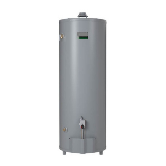
ULTRA LOW NOX COMMERCIAL GAS WATER HEATERS
500 Tennessee Waltz Parkway
Ashland City, TN 37015
Low Lead Content
WARNING: If the information in these
instructions is not followed exactly, a fire
or explosion may result causing property
damage, personal injury or death.
Do not store or use gasoline or other
flammable vapors and liquids in the
vicinity of this or any other appliance.
WHAT TO DO IF YOU SMELL GAS:
•
Do not try to light any appliance.
•
Do not touch any electrical switch; do
not use any phone in your building.
•
Immediately call your gas supplier
from a neighbor's phone. Follow the
gas supplier's instructions.
•
If you cannot reach your gas supplier,
call the fire department.
Installation and service must be
performed by a qualified installer,
service agency or the gas supplier.
PLACE THESE INSTRUCTIONS ADJACENT TO HEATER AND NOTIFY OWNER TO KEEP FOR FUTURE REFERENCE.
KEEP THIS MANUAL IN THE POCKET ON HEATER FOR FUTURE REFERENCE
PRINTED 1215
WHENEVER MAINTENANCE ADJUSTMENT OR SERVICE IS REQUIRED.
Instruction Manual
INSTALLATION - OPERATION - SERVICE
- MAINTENANCE - LIMITED WARRANTY
•
For Your Safety
AN ODORANT IS ADDED TO THE GAS USED
BY THIS WATER HEATER.
1
MODELS BL-80/BL-100
Series 100
Read and understand this instruction
manual and the safety messages
herein before installing, operating or
servicing this water heater.
Failure to follow these instructions and
safety messages could result in death
or serious injury.
This manual must remain with the
water heater.
•
324258-002
Advertisement
Table of Contents

Related Manuals for A.O. Smith BL-80


Summary of Contents for A.O. Smith BL-80
- Page 1 Instruction Manual ULTRA LOW NOX COMMERCIAL GAS WATER HEATERS MODELS BL-80/BL-100 Series 100 INSTALLATION - OPERATION - SERVICE - MAINTENANCE - LIMITED WARRANTY 500 Tennessee Waltz Parkway Ashland City, TN 37015 Low Lead Content WARNING: If the information in these...
-
Page 2: Table Of Contents
TABLE OF CONTENTS SAFE INSTALLATION, USE AND SERVICE...... 3 Outdoor Air Through Two Horizontal Ducts ....14 APPROVALS ..............3 Outdoor Air Through Two Vertical Ducts ....14 GENERAL SAFETY INFORMATION ........4 Air From Other Indoor Spaces ........14 INTRODUCTION ..............5 Venting ..............14 Abbreviations Used ............. 5 Gas Piping ..............16 Qualified Installer or Service Agency......5 Sediment Traps ............ -
Page 3: Safe Installation, Use And Service
SAFE INSTALLATION, USE AND SERVICE The proper installation, use and servicing of this water heater is extremely important to your safety and the safety of others. Many safety-related messages and instructions have been provided in this manual and on your own water heater to warn you and others of a potential injury hazard. Read and obey all safety messages and instructions throughout this manual. It is very important that the meaning of each safety message is understood by you and others who install, use, or service this water heater. This is the safety alert symbol. It is used to alert you to potential personal injury hazards. Obey all safety messages that follow this symbol to avoid possible injury or death. DANGER indicates an imminently hazardous situation which, if not avoided, DANGER... -
Page 4: General Safety Information
GENERAL SAFETY INFORMATION... -
Page 5: Introduction
INTRODUCTION Thank You for purchasing this water heater. Properly installed and properly. It could cause DEATH, SERIOUS BODILY INJURY maintained, it should give you years of trouble free service. AND/OR PROPERTY DAMAGE. This manual contains instructions for the installation, ABBREVIATIONS USED operation, and maintenance of the gas-fired water heater. It also contains warnings throughout the manual that you must Abbreviations Found In This Instruction Manual: read and be aware of. All warnings and all instructions are • UL - Underwriters Laboratories Inc. essential to the proper operation of the water heater and your • ANSI - American National Standards Institute safety. Since we cannot put everything on the first few pages, • NFPA - National Fire Protection Association READ THE ENTIRE MANUAL BEFORE ATTEMPTING TO • ASME - American Society of Mechanical Engineers INSTALL OR OPERATE THE WATER HEATER. • AHRI - Air-Conditioning, Heating and Refrigeration Institute 2. The installation must conform with these instructions and •... -
Page 6: Installation Considerations
15 3/16 15 3/4 1 1/4 1 1/4 11 15/16 Natural 179.1 168.9 78.6 70.5 38.6 10.2 40.0 40.6 30.3 BL-80 Inches 62 1/16 29 1/2 25 1/4 15 7/8 15 1/4 12 1/2 Natural 157.6 147.3 74.9 64.1 40.3 10.2 38.7... -
Page 7: Thermometers
THERMOMETERS (Not Supplied) the structure. For this reason, it is not advisable to install water heater in an attic or upper floor. When such locations cannot be avoided, a Thermometers should be obtained and field installed. suitable metal drain pan should be installed under the water heater. Metal Drain pans are available at your local hardware store. Such a Thermometers are installed in the system as a means of detecting metal drain pan must have a minimum length and width of at least the temperature of the outlet water supply. 2” (51 mm) greater than water heater dimensions and must be piped to an adequate drain. The pan must not restrict combustion air flow. Water heater life depends upon water quality, water pressure and the environment in which the water heater is installed. Water heaters are sometimes installed in locations where leakage may result in property damage, even with the use of a drain pan piped to a drain. However, unanticipated damage can be reduced or prevented by a leak detector or water shut-off device used in conjunction with a piped drain pan. These devices are available from some plumbing supply wholesalers and retailers, and detect and react to leakage in various ways: • Sensors mounted in the drain pan that trigger an alarm or turn off the incoming water to the water heater when leakage is detected. • Sensors mounted in the drain pan that turn off the water supply to the entire home when water is detected in the drain pan. • Water supply shut-off devices that activate based on the water pressure differential between the cold water and hot water pipes connected to the water heater. • Devices that will turn off the gas supply to a gas water heater This Water Heater has been design certified as complying with while at the same time shutting off its water supply. ANSI Z21.10.3-CSA 4.3 current edition for water heaters and is considered suitable for: Water (Potable) Heating and Space Heating: All models are considered suitable for water (potable) heating and space heating. -
Page 8: High Altitude
CLEARANCES used in the same room or area containing a gas water heater or other open flame or spark producing appliance. NOTE: Flammable vapors may be drawn by air currents from other areas of the structure to the appliance. Minimum clearances between the water heater and combustible Also, the water heater must be located and/or protected so it is not construction are 0 inch at the sides and rear, 4” (102 mm) for BL- subject to physical damage by a moving vehicle. 100 and 5” (127 mm) for BL-80 at the front, and 6” (153 mm) from the vent pipe. Clearance from the top of the jacket is 12” (305 mm). FIGURE 2. This water heater must not be installed directly on carpeting. Carpeting must be protected by metal or wood panel beneath the water heater extending beyond the full width and depth of the water heater by at least 3” (76.2 mm) in any direction, or if the water heater is installed in an alcove or closet, the entire floor must be covered by the panel. Failure to heed this warning may result in a fire hazard. HIGH ALTITUDE A gas water heater cannot operate properly without the correct amount of air for combustion. Do not install in a confined area such as a closet, unless you provide air as shown in the Facts to Consider About The Location section. Never obstruct the flow of... -
Page 9: Insulation Blankets
INSULATION BLANKETS CIRCULATION PUMPS A circulating pump is used when a system requires a circulating loop or there is a storage tank used in conjunction with the water heater. See Water Piping Diagrams in this manual for installation location of circulating pumps. Breathing Hazard - Carbon Monoxide Gas See the Circulation Pump Wiring Diagrams below for electrical Do not obstruct water heater air intake hookup information. Install in accordance with the current with insulating blanket. -
Page 10: Installation Requirements
GAS PRESSURE REQUIREMENTS at the water heater or at hot water taps to further reduce system water temperature. See Figure 6. BL-100 natural gas model requires a minimum gas supply pressure of Mixing valves are available at plumbing supply stores. Consult 5” w.c. (1.25 kPa); BL-80 natural gas model requires a minimum gas a Qualified Installer or Service Technician. Follow mixing valve supply pressure of 6” w.c. (1.49 kPa). The minimum supply pressure manufacturer’s instructions for installation of the valves. is measured while gas is flowing (dynamic pressure). The supply pressure (dynamic) should never fall below the specified minimum TABLE 2. -
Page 11: Water Piping
WATER PIPING WATER (POTABLE) HEATING AND SPACE HEATING This water heater shall not be connected to any heating systems or component(s) used with a non-potable water heating appliance. All piping components connected to this unit for space heating applications shall be suitable for use with potable water. Toxic chemicals, such as those used for boiler treatment shall not be introduced into this system. When the system requires water for space heating at temperatures higher than required for domestic water purposes, a mixing valve must be installed. Please refer to Figure 6 for suggested piping arrangement. These water heaters cannot be used in space heating applications FIGURE 7. only. NOTE: To protect against untimely corrosion of hot and cold water fittings, it is strongly recommended that di-electric unions CLOSED WATER SYSTEMS or couplings be installed on this water heater when connected to copper pipe. Water supply systems may, because of code requirements or Figure 7 shows the typical attachment of the water piping to the such conditions as high line pressure, among others, have water heater. -
Page 12: Filling The Water Heater
NOTE: The purpose of a Temperature-Pressure Relief Valve is to NOTE: In addition to the factory installed Temperature-Pressure prevent excessive temperatures and pressures in the storage tank. Relief Valve on the water heater, each remote storage tank that The T&P valve is not intended for the constant relief of thermal may be installed and piped to a water heating appliance must also expansion. A properly sized thermal expansion tank must be installed have its own properly sized, rated and approved Temperature- on all closed systems to control thermal expansion, see Closed Pressure Relief Valve installed. Call the toll free technical support Water Systems and Thermal Expansion on page 11. -
Page 13: Unconfined Space
OUTDOOR AIR THROUGH TWO OPENINGS amount of combustion air can result in a fire or explosion and cause property damage, serious bodily injury or death. UNCONFINED SPACE An Unconfined Space is one whose volume is not less than 50 cubic feet per 1,000 Btu/hr (4.8 cubic meters per kW) of the total input rating of all appliances installed in the space. Rooms communicating directly with the space, in which the appliances are installed, through openings not furnished with doors, are considered a part of the unconfined space. -
Page 14: Outdoor Air Through Two Horizontal Ducts
OUTDOOR AIR THROUGH TWO HORIZONTAL DUCTS enclosure. The vertical ducts shall communicate directly with the outdoors. See Figure 11. Each duct opening shall have a minimum free area of 1 square inch per 4,000 Btu/hr (550 mm2 per kW) of the aggregate input rating of all appliances installed in the enclosure. When ducts are used, they shall be of the same cross sectional area as the free area of the openings to which they connect. The minimum dimension of rectangular air ducts shall be not less than 3 inches. AIR FROM OTHER INDOOR SPACES FIGURE 10. The confined space shall be provided with two permanent horizontal ducts, one commencing within 12 inches (300 mm) of the top and one commencing within 12 inches (300 mm) of the bottom of the enclosure. The horizontal ducts shall communicate directly with the outdoors. See Figure 10. - Page 15 If the water heater is being installed as a replacement for an The vent pipe from the water heater must be no less than the existing heater in pre-existing venting, a thorough inspection of diameter of the draft hood outlet on the water heater and must existing venting system must be performed prior to any installation slope upward at least 1/4 inch per linear foot (21 mm per meter). work.
-
Page 16: Gas Piping
GAS PIPING TABLE 4. NOMINAL IRON PIPE SIZES (INCHES) LENGTH INPUT IN KW METERS 1/2" 3/4" 1" 1 1/4" 1 1/2" 2" 2 1/2" 3" 4" 1160 1845 3221 6735 1277 2255 4626 1031 1830 3748 1552 3192 1391 2840 1259 2577 1142... -
Page 17: Sediment Traps
SEDIMENT TRAPS Contaminants in the gas lines may cause improper operation of the gas control valve that may result in fire or explosion. Before A sediment trap shall be installed as close to the inlet of the water attaching the gas line be sure that all gas pipe is clean on the heater as practical at the time of water heater installation. The inside. To trap any dirt or foreign material in the gas supply line, sediment trap shall be either a tee fitting with a capped nipple a sediment trap must be incorporated in the piping. The sediment in the bottom outlet or other device recognized as an effective trap must be readily accessible. Install in accordance with the sediment trap. If a tee fitting is used, it shall be installed in “Gas Piping” section. Refer to the current edition of the National conformance with one of the methods of installation shown in Fuel Gas Code, ANSI Z223.1/NFPA 54 or the Natural Gas and... -
Page 18: Lighting & Operating Instructions
FOR YOUR SAFETY READ BEFORE LIGHTING WARNING: If you do not follow these instructions exactly, a fire or explosion may result causing property damage, personal injury or loss of life. FLAMMABLE BEFORE LIGHTING: ENTIRE SYSTEM MUST BE FILLED WITH WATER AND AIR PURGED FROM ALL LINES This appliance has a pilot which is lit by a piezo- If you cannot reach your gas supplier, call the fire electric spark gas ignition system. -
Page 19: Temperature Regulation
TEMPERATURE REGULATION Short repeated heating cycles caused by small hot water uses can Never allow small children to use a hot water tap, or to draw their own bath water. Never leave a child or handicapped person unattended cause temperatures at the point of use to exceed the thermostat in a bathtub or shower. setting by up to 30°F (16.7°C). If you experience this type of use you should consider using lower temperature settings to reduce NOTE: A water temperature range of 120°F-140°F (49°C-60°C) is scald hazards. recommended by most dishwasher manufacturers. Any water heater’s intended purpose is to heat water. Hot water The thermostat of this water heater has been factory set at its lowest is needed for cleansing, cleaning, and sanitizing (bodies, dishes, position (PILOT LIGHTING). It is adjustable and must be reset to... -
Page 20: Operational Conditions
BTU Per Approx. Time Required To Model Type of Gas Cu. Ft. Consume 1 Cu. Ft. of Gas a. A concentration of sulfate in the supply water. BL-80 Natural 1050 50.3 sec. BL-100 b. Little or no dissolved oxygen in the water. c. A sulfate reducing bacteria which has accumulated within the Use this formula to “clock” the meter. Be sure that other gas water heater (this harmless bacteria is nontoxic to humans). -
Page 21: Periodic Maintenance
PERIODIC MAINTENANCE VENTING SYSTEM INSPECTION sooting can result in a fire causing death, serious injury, or property damage. Flame Characteristics Correct Flame Red/Orange FIGURE 19. Natural Gas (Low Nox) Burner Door Assembly Use brush on this surface Burner Pilot Assembly At least once a year a visual inspection should be made of the venting system. You should look for: 1. Obstructions which could cause improper venting. The combustion and ventilation air flow must not be obstructed. -
Page 22: Anode Rod Inspection
INSTALLED IN SUITABLE AREA: To insure sufficient ventilation When checking the Temperature-Pressure Relief Valve operation, and combustion air supply, proper clearances from the water make sure that (1) no one is in front of or around the outlet of the heater must be maintained. See Facts to Consider About The Temperature-Pressure Relief Valve discharge line, and (2) that the water discharge will not cause any property damage, as the water Location section. Combustible materials such as clothing, may be extremely hot. Use care when operating valve as the valve cleaning materials, or flammable liquids, etc. must not be placed may be hot. against or adjacent to the water heater which can cause a fire. To check the relief valve, lift the lever at the end of valve several times, ANODE ROD INSPECTION see Figure 21. The valve should seat properly and operate freely. If after manually operating the valve, it fails to completely reset and CAUTION continues to release water, immediately close the cold water inlet to the water heater and drain the water heater, see Draining And Property Damage Hazard... -
Page 23: Deliming Solvents
Lime accumulation not only reduces the life of the equipment but 1. Drain heater. also reduces efficiency of the heater and increases fuel consumption. 2. Remove outer cover plate from lower side of heater jacket. The usage of water softening equipment greatly reduces the 3. Remove six (6) hex head screws securing tank cleanout plate hardness of the water. However, this equipment does not always and remove plate. remove all of the hardness (lime). For this reason it is recommended that a regular schedule for deliming be maintained. 4. Remove lime, scale, or sediment using care not to damage the glass lining. The time between cleaning will vary from weeks to months depending upon water conditions and usage. 5. Inspect cleanout plate gasket, if new gasket is required, see replacement parts list for item number. The depth of lime buildup should be measured periodically. Heaters equipped with cleanouts will have about 2” of lime buildup when 6. Install cleanout plate. Be sure to draw plate up tight by tightening the level of lime has reached the bottom of the cleanout opening. A... -
Page 24: Draining And Flushing
4. Put cap with male adapter back on the container and slide 3/4” Ensure the cold water inlet valve is open. hose over end of male adapter and fasten in place using hose Open a nearby hot water faucet and let the water run until clamp provided. the water is no longer hot. DELIME USING FLO-JUG METHOD Close the cold water inlet valve to the water heater. Connect a hose to the water heater drain valve and 5. Slide the hose clamp over end of hose and slide hose over the terminate it to an adequate drain. male adapter in the water heater drain opening and secure in Open the water heater drain valve and allow all the water to place using hose clamp. -
Page 25: Leakage Checkpoints
LEAKAGE CHECKPOINTS A. Water at the draft hood is water vapor which has condensed out of the combustion products. This is caused by a problem in the vent. Contact the gas utility. B. *Condensation may be seen on pipes in humid weather or pipe connections may be leaking. C. *The anode rod fitting may be leaking. D. Small amounts of water from temperature-pressure relief valve may be due to thermal expansion or high water pressure in your area. E. *The temperature-pressure relief valve may be leaking at the tank fitting. F. Water from a drain valve may be due to the valve being slightly opened. G. * The drain valve may be leaking at the tank fitting. H. Combustion products contain water vapor which can condense on the cooler surfaces of the tank. Droplets form and drip onto the burner or run on the floor. This is common at the time of start-up after installation and when incoming water is cold. I. Water in the water heater bottom or on the floor may be from condensation, loose connections, or the relief valve. DO NOT replace the water heater until a full inspection of all possible water sources is made and necessary corrective steps taken. Leakage from other appliances, water lines, or ground seepage should also be checked. -
Page 26: Troubleshooting Guidelines
TROUBLESHOOTING GUIDELINES These guidelines should be utilized by a qualified service agent. Problem Cause Solution Improperly sealed, hot or cold supply connection, relief Tighten threaded connections. valve, drain valve, or thermostat threads. WATER LEAKS Leakage from other appliances or water lines. Inspect other appliances near water heater. Condensation of flue products. Refer to CONDENSATION. Thermal expansion in closed water system. Install thermal expansion tank (DO NOT plug T&P valve). LEAKING T&P VALVE Check relief valve for proper operation Improperly seated valve. (DO NOT plug T&P valve). High sulfate or mineral content in water supply. Drain and flush heater thoroughly, then refill. SMELLY WATER Bacteria in water supply. Chlorinate or aerate water supply. Gas control knob not positioned correctly. Refer to LIGHTING INSTRUCTIONS. Main gas supply off. Turn on main gas shutoff valve. PILOT WILL NOT LIGHT Thermocouple malfunction. -
Page 27: Water Piping Diagrams
WATER PIPING DIAGRAMS... -
Page 33: Notes
NOTES... - Page 34 NOTES...
-
Page 35: Warranty
LIMITED WARRANTY COMMERCIAL WATER HEATER LIMITED WARRANTY EFFECTIVE WHAT'S NOT COVERED For 3 Years, in the event of a tank leak, we will repair or, at our • Problems caused by improper: gas supply line sizing, gas type, discretion, replace the defective water heater. venting, connections, combustion air, voltage, wiring, or fusing For 1 Year, •... - Page 36 500 Tennessee Waltz Pkwy., Ashland City, TN 37015 Technical Support: 800-527-1953 • Parts: 800-433-2545 www.hotwater.com Copyright © 2014 A. O. Smith Corporation, All rights reserved.
Need help?
Do you have a question about the BL-80 and is the answer not in the manual?
Questions and answers