Table of Contents
Advertisement
Ashland City, TN 37015
www.hotwater.com
all technIcal and warrantY questIons: SHOULD BE DIRECTED TO THE LOCAL DEALER FROM WHOM THE WATER HEATER WAS
PURCHASED. IF YOU ARE UNSUCCESSFUL, CALL THE TECHNICAL SUPPORT PHONE NUMBER SHOWN ON THE WATER HEATER LABELING.
PRINTED IN THE U.S.A 0408
coMMercIal Gas water heaters
Keep thIs Manual In the pocKet on heater for future reference
whenever MaIntenance adjustMent or servIce Is requIred.
Instruction Manual
power vent/power dIrect vent Gas Models
•
for Your safety
AN ODORANT IS ADDED TO THE GAS USED
BY THIS WATER HEATER.
1
wIth hot surface IGnItIon
•
197833-000
Advertisement
Table of Contents

Related Manuals for A.O. Smith Commercial gas water heaters


Summary of Contents for A.O. Smith Commercial gas water heaters
-
Page 1: Instruction Manual
Instruction Manual coMMercIal Gas water heaters power vent/power dIrect vent Gas Models wIth hot surface IGnItIon Ashland City, TN 37015 www.hotwater.com • • for Your safety AN ODORANT IS ADDED TO THE GAS USED BY THIS WATER HEATER. all technIcal and warrantY questIons: SHOULD BE DIRECTED TO THE LOCAL DEALER FROM WHOM THE WATER HEATER WAS PURCHASED. -
Page 2: Safe Installation, Use And Service
safe InstallatIon, use and servIce Your safety and the safety of others is extremely important in the installation, use and servicing of this water heater. Many safety-related messages and instructions have been provided in this manual and on your own water heater to warn you and others of a potential injury hazard. -
Page 3: General Safety
General safetY... - Page 4 General safetY...
-
Page 5: Table Of Contents
taBle of contents SAFE INSTALLATION, USE AND SERVICE......2 Installation Sequence............21 GENERAL SAFETY..............3 Vertical Vent Terminal Installation ........21 TABLE OF CONTENTS ............5 Installation of Vent System, Sidewall ......22 INTRODUCTION ..............5 Installation of Vertical Vent System .........22 Preparing for the Installation ..........5 Vent Pipe Preparation .............26 Get to Know Your Water Heater ........6 Controls and Switches ............28 INSTALLATION CONSIDERATIONS ........7 Power Vent Wiring Schematic.........29 Rough In Dimensions............7 LIGHTING &... -
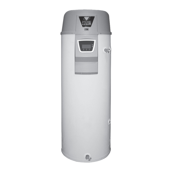
Page 6: Get To Know Your Water Heater
Get to Know Your water heater - Gas Models control assembly Inlet dip tube display enclosure Blocked Inlet switch ** n exhaust elbow assembly T/P Relief Valve Blocked outlet switch ** o condensate tubing aa rating plate fan prover switch off/on switch BB labels Blower assembly... -
Page 7: Installation Considerations
InstallatIon consIderatIons rouGh In dIMensIons FIGURE 1A. rough-In-dimensions Model Units Inches 68.50 49.25 22.00 15.75 3.00 8.00 125.09 55.88 40.00 7.62 20.32 Top/Side Inlet and Outlet: 3/4” NPT Gas Inlet: 1/2” NPT capacity, Gas and electrical characteristics Approximate Capacity Manifold Pressure Electrical Characteristics Model U.S. -
Page 8: Commonwealth Of Massachusetts
InstallatIon requIreMents for the coMMonwealth of Massachusetts For all side wall terminated, horizontally vented power vent, direct vent, and power direct vent gas fueled water heaters installed in every dwelling, building or structure used in whole or in part for residential purposes, including those owned or operated by the Commonwealth and where the side wall exhaust vent termination is less than seven (7) feet above finished grade in the area of the venting, including but not limited to decks and porches, the following requirements shall be satisfied: InstallatIon of carBon MonoXIde detectors At the time of installation of the side wall horizontal vented gas fueled equipment, the installing plumber or gasfitter shall observe that a hard wired carbon monoxide detector with an alarm and battery back-up is installed on the floor level where the gas equipment is to be installed. In addition, the installing plumber or gasfitter shall observe that a battery operated or hard wired carbon monoxide detector with an alarm is installed on each additional level of the dwelling, building or structure served by the sidewall horizontal vented gas fueled equipment. It shall be the responsibility of the property owner to secure the services of qualified licensed professionals for the installation of hard wired carbon monoxide detectors. In the event that the side wall horizontally vented gas fueled equipment is installed in a crawl space or an attic, the hard wired carbon monoxide detector with alarm and battery back-up may be installed on the next adjacent floor level. In the event that the requirements of this subdivision can not be met at the time of completion of installation, the owner shall have a period of thirty (30) days to comply with the above requirements provided that during said thirty (30) day period, a battery operated carbon monoxide detector with an alarm shall be installed. approved carBon MonoXIde detectors Each carbon monoxide detector as required in accordance with the above provisions shall comply with NFPA 720 and be ANSI/UL 2034 listed and CSA certified. sIGnaGe A metal or plastic identification plate shall be permanently mounted to the exterior of the building at a minimum height of eight (8) feet above grade directly in line with the exhaust vent terminal for the horizontally vented gas fueled heating appliance or equipment. The sign shall read, in print size no less than one-half (1/2) inch in size, “Gas vent dIrectlY Below. Keep clear of all oBstructIons.” InspectIon The state or local gas inspector of the side wall horizontally vented gas fueled equipment shall not approve the installation unless, upon inspection, the inspector observes carbon monoxide detectors and signage installed in accordance with the provisions of 248 CMR 5.08(2)(a) 1 through 4. -
Page 9: Water Piping - Mixing Valve Usage
water pIpInG - MIXInG valve usaGe * the side recirculation loop connections may not be used as the primary water inlet and outlet connections. for your convenience, plugs are installed in these fittings at the factory. Remove these plugs if needed for your specific installation. Otherwise (as with all connections) check for leaks while filling the tank with water and after completing the installation. -
Page 10: Facts To Consider About The Location
facts to consIder aBout the locatIon Carefully choose an indoor location for the new water heater, because the placement is a very important consideration for the safety of the occupants in the building and for the most economical use of the appliance. this water heater is not for use in manufactured (mobile) homes or outdoor installation. Whether replacing an old water heater or putting the water heater in a new location, the following critical points must be observed: 1. Select a location indoors as close as practical to the vent terminal or location to which the water heater vent piping is going to be connected, and as centralized with the water piping system as possible. 2. Selected location must provide adequate clearances for servicing and proper operation of the water heater. -
Page 11: Facts To Consider About Location
in an alcove or closet, the entire floor must be covered by the panel. for placement on the blanket directly over the existing labels. • Do inspect the insulation blanket frequently to make certain it Failure to heed this warning may result in a fire hazard. does not sag, thereby obstructing combustion air flow. coMBustIon aIr and ventIlatIon A gas water heater cannot operate properly without the correct amount of air for combustion. Do not install in a confined area such as a closet, unless you provide air as shown in the “Facts to Consider About Location” section. Never obstruct the flow of ventilation air. If you have any doubts or questions at all, call your gas supplier. Failure to provide the proper amount of combustion air can result in a fire or explosion and cause death, serious bodily injury, or property damage. Minimum clearances between the water heater and combustible construction are 0 inch at the sides and rear, 5.5” (14.0 cm) from the front and 12” (30.5 cm) from the top. (Standard clearance.) If clearances stated on the heater differ from standard clearances, install water... - Page 12 a free area of one square inch per 1000 Btu/hr (22 cm /kW) of the Btu per hour (11 cm2/kW)) of total input rating of all equipment in the total input of all appliances in the enclosure, but not less than 100 enclosure, see Figure 9. square inches (645 cm If the confined space is within a building of tight construction, air for combustion and ventilation must be obtained from outdoors. When directly communicating with the outdoors or communicating through vertical ducts, two permanent openings, located in the above manner, shall be provided. Each opening shall have a free area of not less than one square inch per 4000 Btu/hr (5.5 cm /kW) of total input of all appliances in the enclosure. If horizontal ducts are used, each opening shall have a free area of not less than one square inch per 2000 Btu/ hr (11cm /kW) of the total input of all appliances in the enclosure. a. all aIr froM InsIde BuIldInGs: (See Figure 5 and 6) The confined space shall be provided with two permanent openings communicating directly with an additional room(s) of sufficient volume so that the combined volume of all spaces meets the criteria for an unconfined space. The total input of all gas utilization equipment installed in the combined space shall be considered in making this determination.
-
Page 13: Installing The Water Heater
InstallInG the new water heater closed water sYsteMs cheMIcal vapor corrosIon Water supply systems may, because of code requirements or such CORROSION OF THE FLUEWAYS AND VENT SYSTEM MAY OCCUR IF AIR FOR COMBUSTION CONTAINS CERTAIN CHEMICAL VAPORS. SUCH conditions as high line pressure, among others, have installed devices CORROSION MAY RESULT IN FAILURE AND RISK OF ASPHYXIATION. -
Page 14: Temperature-Pressure Relief Valve
Figures 2 and 10 show the typical attachment of the water piping to If replaced, the valve must meet the requirements of local codes, but the water heater. The water heater is equipped with 3/4 inch NPT not less than a combination temperature and pressure relief valve water connections. certified as indicated in the above paragraph. The valve must be marked with a maximum set pressure not to note: If using copper tubing, solder tubing to an adapter exceed the marked hydrostatic working pressure of the water heater before attaching the adapter to the water heater connections. -
Page 15: Gas Piping
hIGh altItude InstallatIons The temperature-pressure relief valve must be manually operated at least once a year , see Figure 28. Caution should be taken to ensure that (1) no one is in front of or around the outlet of the temperature-pressure relief valve discharge line, and (2) the water manually discharged will not cause any bodily injury or property damage because the water may be extremely hot. If after manually operating the valve, it fails to completely reset and continues to release water, immediately close the cold water inlet to the water heater, follow the draining instructions, and replace the temperature-pressure relief valve with a new one. Gas pIpInG Rated inputs are suitable up to 10,100 feet (3,079m) elevation. Consult the factory for installation at altitudes over 10,100 feet (3,079m). WARNING: THIS HIGH EFFICIENCY WATER HEATER IS CERTIFIED FOR USE WITHOUT MODIFICATION FOR AN ALTITUDE OF 10,100 FEET (3,079 METERS). INSTALLATIONS ABOVE THESE ALTITUDES MAY REQUIRE REPLACEMENT OF BURNER ORIFICE. -
Page 16: Sediment Traps
ventInG sedIMent traps A sediment trap shall be installed as close to the gas inlet of the water heater as practical at the time of water heater installation. The sediment trap shall be either a tee fitting with a capped nipple in the bottom outlet or other device recognized as an effective sediment trap. Contaminants in the gas lines may cause improper operation of the gas control valve that may result in fire or explosion. Before attaching the gas line be sure that all gas pipe is clean on the inside. To trap any dirt or foreign material in the gas supply line, a drip leg (sometimes called a sediment trap) must be incorporated in the piping. The drip leg must be readily accessible. Install in accordance with the “Gas Piping” section. Refer to the current edition of the National Fuel Gas Code (ANSI Z223.1/NFPA 54) or the Natural Gas and Propane vent pIpe terMInatIon Installation Code (CAN/CSA B149.1). fIllInG the water heater The first step is to determine where the vent pipe will terminate. See Figures 19, 20, and 21. The vent may terminate through a sidewall as shown in Figure 19 or through the roof as shown in Figures 20 and 21. The vent system must terminate so that proper clearances are maintained as cited in local codes or the current edition of the National Fuel Gas Code, (ANSI Z223.1, 12.9.1 through 12.9.4) or the Natural Gas and Propane Installation... - Page 17 u.s. power vent warnInG VENT HOOD(S) MAY BE eXtreMelY hot durInG operatIon. FIGURE 15A. cautIon to prevent eXhaustInG products froM cIrculatInG to the aIr IntaKe In wIndY/cold areas, the MaXIMuM practIcal dIstance Between these two terMInals Is recoMMended. canadIan power vent warnInG VENT HOOD(S) MAY BE eXtreMelY hot...
- Page 18 u.s. dIrect vent warnInG VENT HOOD(S) MAY BE eXtreMelY hot durInG operatIon. FIGURE 15C. cautIon to prevent eXhaustInG products froM cIrculatInG to the aIr IntaKe In wIndY/cold areas, the MaXIMuM practIcal dIstance Between these two terMInals Is recoMMended. canadIan dIrect vent warnInG VENT HOOD(S) MAY BE eXtreMelY hot...
-
Page 19: Planning The Vent System
plannInG the vent sYsteM of existing venting system must be performed prior to any installation work. Verify that correct material as detailed above has been used, and that the minimum or maximum vent lengths and terminal location Plan the route of the vent system from the exhaust elbow to the as detailed in this manual have been met. Carefully inspect the entire planned location of the vent terminal. venting system for any signs of cracks or fractures, particularly at 1. Layout total vent system to use a minimum of vent pipe and elbows. joints between elbows and other fittings and straight runs of vent 2. This water heater is capable of venting flue gases equivalent to pipe. Check system for signs of sagging or other stresses in joints as 25’ (7.6 m) of 2” pipe, 65’ (19.8 m) of 3” pipe, or 128’ (39.0 m) of a result of misalignment of any components in the system. If any of 4” pipe as listed in Table 1. these conditions are found, they must be corrected in accordance with the venting instructions in this manual before completing installation TABLE 1 and putting the water heater into service. Number of 2” Maximum 3”... -
Page 20: Installation Of Vent System
InstallatIon of vent sYsteM dIrect ventInG The air intake provided on the unit contains a mesh screen to prevent Before beginning installation of piping system thoroughly read large particles from entering the unit. the section of this manual VENT PIPE PREPARATION. If you are installing your system so that it vents through roof, please refer to section titled INSTALLATION OF VERTICAL VENT SYSTEM. vent terMInal InstallatIon, sIdewall 1. Install the vent terminal by using the cover plate as a template to mark the hole for the vent pipe to pass through the wall. BEWARE OF CONCEALED WIRING AND PIPING INSIDE THE WALL. -
Page 21: Installation Sequence
InstallatIon sequence vertIcal vent terMInal InstallatIon For installations in the City of Los Angeles, California Category IV IMportant PVC Pipe such as that manufactured by Brownline Pipe Company, when terMInatInG throuGh a roof, the followInG must be used as vent pipe material. specIfIcatIons pertaInInG to terMInal locatIon cautIon Must Be followed. vent terMInals supplIed wIth heater Must Be used. 1. Proper support must be provided for all pipe protruding through NOTE: BEFORE BEGINNING INSTALLATION OF ANY the roof. -
Page 22: Installation Of Vent System, Sidewall
InstallatIon of vent sYsteM, sIdewall With the route of the venting system and selection of materials completed, as discussed in the section of this manual titled PLANNING THE VENT SYSTEM, the through the wall vent terminal in place and the first section of piping, up to first elbow, installed at the blower it is time to complete the installation of the venting system for the sidewall installation. FIGURE 23. IMportant The vent system must terminate so that proper clearances are maintained as cited in local codes or the current edition of the National Fuel Gas Code (ANSI Z223.1) or the Natural Gas and FIGURE 22. Propane Installation Code (CAN/CSA-B149.1) and as listed below: Before completing the installation of the venting system be sure to read 1. Vent Termination must extend a minimum of 18 inches (46 cm) above the sections of this manual discussing the proper method of cutting and roof or 18 inches (46 cm) above the anticipated snow level to prevent cementing PVC pipe and fittings: VENT PIPE PREPARATION. blockage of the vent termination, as shown in Figures 20 and 21. It is recommended that the completion of the venting system start at the blower assembly and run to the coupling on the inside wall of the concentrIc vent InstallatIon vent terminal, Figure 18A. -
Page 23: Safety Considerations
This concentric vent termination kit may be used with 3 or 4 inch diameter 1. Determine best location for termination kit. pipe systems. When connecting to a 4 in. diameter pipe system a 3 x 4 note: roof termination is preferred since it is less inch field supplied reducer is to be installed at the intake and exhaust susceptible to damage, has reduced chances to intake connection of the concentric vent termination kit. contaminants, and less visible vent vapors. 2. Cut 1 hole (5 in. diameter) safetY consIderatIons 3. Partially assemble concentric vent termination kit. Installing and servicing water heating equipment can be hazardous due to a) Cement Y concentric fitting to larger diameter kit gas and electrical components. Installation and service of the concentric pipe, see Figure A. - Page 24 5. Secure assembly to roof structure as shown in Figure E using NOTE: See the venting information (pages 16-20) in this field supplied metal strapping or equivalent support material. manual for additional vent location requirements. note: ensure termination height is above the roof surface or 2. Cut 1 hole (5 in. diameter) anticipated snow level (1 ft. in U.S.A. or 1-1/2 ft. in Canada) as shown in figure c.
-
Page 25: Multi-Concentric Vent Terminations
8. Operate heater through 1 heat cycle to ensure combustion-air and vent pipes are properly connected to concentric vent termination connections. figure h. Concentric Vent Terminations for Horizontal Direct Venting. fIGure G. MultI-concentrIc vent terMInatIons When two or more appliances are directed vented with concentric vent terminations near each other, each appliance must be individually vented. NEVER common vent this appliance. When two or more appliances are direct vented using concentric vent figure I. -
Page 26: Vent Pipe Preparation
vent pIpe preparatIon prIMer 1. INITIAL PREPARATION. It is recommended that Tetrahydrofuran (THF) be used to prepare the surfaces of pipe and fittings for solvent welding. Do not use water, A.) Make sure the solvent cement you are planning to use is rags, gasoline or any other substitutes for cleaning PVC or CPVC designed for the specific application you are attempting. surfaces. A chemical cleaner such as MEK may be used. B.) Know the physical and chemical characteristics and ceMent limitations of the PVC and CPVC piping materials that you are about to use. - Page 27 B. deburring Use a knife, plastic pipe deburring tool, or file to remove burrs from the end of small diameter pipe. Be sure to remove all burrs from around the inside as well as the outside of the pipe. A slight chamfer (bevel) of about 10°-15° should be added to the end to permit easier insertion of the pipe into the end of the fitting. Failure to chamfer the edge of the pipe may remove cement from the fitting socket, causing the joint to leak. step B C. Test dry fit of the joint step e Tapered fitting sockets are designed so that an interfaced fit should f. joint assembly occur when the pipe is inserted about 1/3 to 2/3 of the way into the Working quickly, insert the pipe into the fitting socket bottom and socket. Occasionally, when pipe fitting dimensions are at the tolerance give the pipe or fitting a 1/4 turn to evenly distribute the cement. extremes, it will be possible to fully insert dry pipe to the bottom of Do not continue to rotate the pipe after it has hit the bottom of the the fitting socket. When this happens, a sufficient quantity of cement fitting socket. A good joint will have sufficient cement to make a must be applied to the joint to fill the gap between the pipe and fitting. bead all the way around the outside of the fitting hub. The fitting The gap must be filled to obtain a strong, leak-free joint. will have a tendency to slide back while the cement is still wet so hold the joint together for about 15 seconds. d. Inspection, cleaning, priming Visually inspect the inside of the pipe and fitting sockets and remove all dirt, grease or moisture with a clean dry rag. If wiping fails to clean the surfaces, a chemical cleaner must be used.
-
Page 28: Controls And Switches
controls and swItches open. When this switch prevents the unit from igniting, most likely the exhaust is blocked by some means. Check to see if the condensate is allowed to flow freely from the exhaust elbow and for obstructions This model is provided with three pressure switches. These switches in the exhaust venting and exhaust vent terminal. Also verify that are essential to the safe and proper operation of the unit. All switches are wired in series. The controller is set up to shut the unit down the vent length does not exceed the maximum allowed as shown in whenever there is a failure of any of the switches. It is important to the Vent Section of this manual. understand the purpose of each switch. BlocKed IntaKe swItch (SEE FIGURE 12) The Blocked Intake Switch is set up to shut the unit off when a build-up of negative pressure in the intake air pipe occurs. This switch is a negative pressure switch that requires an increase in negative pressure to change the electrical contacts from normally closed to open. The switch is connected to the pressure tap on the PVC pipe connected to the inlet of the blower. When this switch prevents the unit from igniting, most likely the intake is blocked. Verify that the screen on the intake air connection (conventional vent), the intake air pipe and termination (direct vent installations) are free of obstructions that may prevent air from entering the unit. Insure the screen on intake air connection has been removed on direct vent installations, see Figure 18B. Also verify the intake air pipe length does not exceed the maximum allowed as shown in the Vent Section of this manual. FIGURE 12. on/off swItch Blower prover swItch The ON/OFF Switch is a single-pole, single-throw rocker switch. This (SEE FIGURE 12) switch provides 120V from the line source to the heater. -
Page 29: Power Vent Wiring Schematic
cautIon LABEL ALL WIRES PRIOR TO DISCONNECTION WHEN SERVICING CONTROLS. WIRING ERRORS CAN CAUSE IMPROPER AND DANGEROUS OPERATION. VERIFY PROPER OPERATION AFTER SERVICING. THIS WATER HEATER IS POLARITY SENSITVE. B EFO R E A PPLYI N G ELECTRICITY TO THIS HEATER BE CERTAIN THAT SUPPLY NEUTRAL WIRE TO GROUND... -
Page 30: Lighting & Operating Label
for Your safetY read Before lIGhtInG warnInG: If you do not follow these instructions exactly, a fire or explosion may result causing property damage, personal injury or loss of life. Before operatInG: entIre sYsteM Must Be fIlled wIth water and aIr purGed froM all lInes. A. This appliance does not have a pilot. It is equipped with • If you cannot reach your gas supplier, call the fire an ignition device which automatically lights the burner. -
Page 31: Temperature Regulation
teMperature reGulatIon It is recommended that lower water temperatures be used to avoid The water temperature is controlled using the Temperature the risk of scalding. It is further recommended, in all cases, that the Control on the Display at the front of the unit (See Figure 1). water temperatures be set for the lowest temperature which satisfies This control utilizes a temperature probe to determine the tank your hot water needs. This will also provide the most energy efficient temperature. The primary temperature probe is located at the operation of the water heater. top of the tank. The temperature may be adjusted from 90°F/32°C to 180°F/82°C. The thermostat was adjusted to 120°F/49°C before the heater was shipped from the factory. It is recommended that lower water temperature be used to avoid the risk of scalding. It is further... -
Page 32: Using The Electronic Controller
usInG the electronIc controller 1. Overview Interaction with the water heater controller is done through an up, a down, and three operation buttons. These buttons are illustrated to the right. Operation of the three lower buttons is defined immediately above them on the screen. The [UP] and [DN] buttons are used to navigate through the menus and make adjustments to the water heater. While the water heater is operating, the user interface will display the desktop screen (if there are no active faults or warnings). An example of this screen is shown to the right. The first temperature on this screen is the temperature of the water inside the tank. The second temperature on this screen is the Operating Set Point. The Operating Set Point is the temperature at which the water heater will maintain the water inside the tank. The third line on the screen is a text description of the Operational State of the water heater (please see Operating States for more details). The following status icons describe graphically operational details of the heater. The legend of all the status icons is listed below. -
Page 33: Operating States
2. Operating States In the main desktop screen, there are some specific Operating States that are indicated on the status line. These are summarized below: Adjusting the Operating Set Point actIon: From the Main Menu, press select to enter the "Temperatures" screen. The Operating Set Point of this water heater determines the regulated temperature for the water in the tank. This parameter is adjusted in the Temperature menu. Items in this menu allow you to monitor different temperature readings in the tank along with adjusting the Operating Set Point. dIsplaY: actIon: From the desktop screen, press Menu. dIsplaY: actIon: Press change then use the up and down buttons to change the Set Point. -
Page 34: Changing The Display Units
3. Changing the Display Units There are two types of conditions that can occur during operation. These are Warnings and Faults: The display interface to the heater has the option of selecting between degrees Fahrenheit and degrees Celsius for temperature displays. • warnings: This is a non-safety related condition that the control has This can be found in the “Display Settings” menu. Also in this menu, detected that may cause the water heater to operate in a less than optimal condition, but does not pose a safety concern. you may adjust how the backlight operates and the contrast of the LCD screen. -
Page 35: Viewing The Fault History
6. Viewing the Fault History actIon: To get to the current fault information screen, press Menu. The controller for this water heater will store a history of ten of the last Fault and Warning conditions that occurred. This is stored in the dIsplaY: Fault History. Along with all the information about the fault, including a estimate time of when the fault occurred, information regarding the advanced diagnostics for that fault can be accessed at any time. actIon: Press the down button for more information. dIsplaY: actIon: Press the down button to highlight "current Fault" and press select. dIsplaY: actIon: Press the down key to scroll through the fault history. If you select a specific fault or warning, you may press the vIew button to view details regarding this fault. -
Page 36: For Your Information
for Your InforMatIon start up condItIons operatIonal condItIons sMellY water sMoKe/odor In each water heater there is installed at least one anode rod (see It is not uncommon to experience a small amount of smoke and parts section) for corrosion protection of the tank. Certain water odor during the initial start-up. This is due to burning off of oil conditions will cause a reaction between this rod and the water. from metal parts, and will disappear in a short while. The most common complaint associated with the anode rod is one of a “rotten egg smell” in the hot water. The smell is a result of four therMal eXpansIon factors which must all be present for the odor to develop: a. A concentration of sulfate in the supply water. -
Page 37: Periodic Maintenance
perIodIc MaIntenance ventInG sYsteM InspectIon water heater will create dangerous conditions which can cause DEATH, SERIOUS BODILY INJURY, OR PROPERTY DAMAGE. Contact a qualified installer or service agency to replace a flooded water heater. Do not attempt to repair the unit! It must be replaced! At least once a year a visual inspection should be made of the main burner and the hot surface igniter assembly for proper flame characteristics and ignition sequences. You should also check for sooting. Soot is not normal and will impair proper combustion. A visual... -
Page 38: Anode Rod Inspection
INSTALLED IN SUITABLE AREA: To insure sufficient ventilation and When checking the temperature-pressure relief valve operation, combustion air supply, proper clearances from the water heater must make sure that (1) no one is in front of or around the outlet of the be maintained. See “Facts to Consider About Location” section. temperature-pressure relief valve discharge line, and (2) that the Combustible materials such as clothing, cleaning materials, or water discharge will not cause any property damage, as the water flammable liquids, etc. must not be placed against or adjacent to may be extremely hot, see Figure 28. the water heater which can cause a fire. If after manually operating the valve, it fails to completely reset and continues to release water, immediately close the cold water inlet anode rod InspectIon to the water heater, follow the draining instructions, and replace the temperature-pressure relief valve with a new one. If the temperature-pressure relief valve on the appliance weeps or discharges periodically, this may be due to thermal expansion. -
Page 39: Service
servIce If you are not thoroughly familiar with gas codes, your water heater, and safety practices, contact your gas supplier or qualified installer If a condition persists or you are uncertain about the operation of to check the water heater. the water heater contact a qualified service agency. Read this manual first. Then before checking the water heater make Use this guide to check a “Leaking” water heater. Many suspected sure the gas supply has been turned “OFF”, and never turn the gas “Leakers” are not leaking tanks. Often the source of the water can “ON” before the tank is completely full of water. be found and corrected. leaKaGe checKpoInts Never use this water heater unless it is completely filled with water. To prevent damage to the tank, the tank must be filled with water. Water must flow from the hot water faucet before turning “ON” gas to the water heater. A *Condensation may be seen on pipes in humid weather or pipe connections may be leaking. B. *The anode rod fitting may be leaking. C. Small amounts of water from temperature-pressure relief valve may be due to thermal expansion or high water pressure in your area. D. *The temperature-pressure relief valve may be leaking at the tank fitting. -
Page 40: Troubleshooting
trouBleshootInG GuIdelInes These guidelines should be utilized by a qualified service agent. proBleMs 1.) Blower will not run. a. “ON/OFF” control switch turned off. Turn switch to the “ON” position. b. Blower unplugged. Plug blower back into 115 VAC outlet. c. No power at outlet. Repair service to outlet. d. Thermostat defective. Replace thermostat. e. Control harness defective. Replace control harness. Reduce the water temperature below 140°F. Turn the power switch to the off position. Wait 10 seconds. Turn the power switch to f. High limit control circuit open. the on position. Reduce the temperature set point to minimize likelihood of reoccurrence. If this does not solve the problem, replace the thermostat. not enouGh hot water g. Blower motor defective. -
Page 41: Notes
notes... - Page 42 notes...
-
Page 43: Warranty
limited warranty A. O. Smith Corporation, the warrantor, extends the following LIMITED WARRANTY to the owner of this water heater. the tanK If the glass-lined tank in this water heater shall prove upon examination by the warrantor to have leaked due to natural corrosion from potable water therein, during the first THREE years after initial installation, the warrantor will supply a complete new A. O. Smith water heater of equivalent size and current model. Some government agencies are requiring energy efficient standards for water heaters. In the event regulations prohibit sale of a model of equivalent size and construction, A. O. Smith will provide a model which complies with the regulations of your area, in which case the consumer will be charged the difference in price between the like replacement and the energy efficient model required. The warranty on the replacement water heater will be limited to the unexpired term of the original warranty. all other parts If within ONE year after initial installation of this water heater, any part or portion shall prove upon examination by the warrantor to be defective in material or workmanship, the warrantor will repair or replace such part or portion at its option. condItIons and eXceptIons This warranty shall apply only when the water heater is installed in accordance with local plumbing and building codes, ordinances and regulations, the printed instructions provided with it and good industry practices. In addition, a temperature and pressure relief valve, certified by and officially sanctioned and recognized independent testing agency and approved by the American Society of Mechanical Engineers, must have been installed. a. This warranty shall apply only when the heater is: (1) used at temperatures not exceeding the maximum calibrated setting of its thermostat; (2) used at water pressure not exceeding the working pressure shown on the heater; (3) filled with potable water, free to circulate at all times and with the tank free of damaging water sediment or scale deposits; (4) used in a non-corrosive and non-contaminated atmosphere; (5) used with factory approved anode(s) installed; (6) in its original installation location; (7) in the United States, its territories or possessions or Canada; (8) sized in accordance with proper sizing techniques for commercial and/or residential water heaters; (9) bearing a rating plate which has not been altered, defaced or removed, except as required by the warrantor;... - Page 44 500 Tennessee Waltz Parkway, Ashland City, TN 37015 Phone: 800-527-1953 Fax: 800-433-2515 www.hotwater.com...
Need help?
Do you have a question about the Commercial gas water heaters and is the answer not in the manual?
Questions and answers