Table of Contents
Advertisement
Quick Links
Advertisement
Table of Contents

Related Manuals for Burkert 6440


Summary of Contents for Burkert 6440
- Page 1 Type 6440 2/2-way solenoid valve, servo-assisted Operating Instructions...
- Page 2 We reserve the right to make technical changes without notice. © Bürkert Werke GmbH & Co. KG, 2023 Operating Instructions 2306/00_ENen_ 00815439 / Original DE...
-
Page 3: Table Of Contents
Type 6440 Contents CONTENTS 1 About this document.......................... 4 Manufacturer ............................ 4 Used symbols ........................... 4 Terms and abbreviations ........................ 5 2 Safety instructions............................ 6 Intended use ............................. 6 Safety.............................. 6 3 Product description............................ 9 Product structure.......................... 9 Type label ............................ 10 4 Technical data ............................ 11 Standards and Directives ....................... -
Page 4: About This Document
Before starting any work on the product, read and observe the respective sections of the document. Keep the document available for reference and give it to the next user. Contact the Bürkert sales office for any questions. Further information concerning the product at country.burkert.com. Manufacturer Bürkert Fluid Control Systems Christian-Bürkert-Str. -
Page 5: Terms And Abbreviations
Type 6440 About this document Terms and abbreviations The terms and abbreviations are used in this document to refer to following definitions. Device 2/2-way solenoid valve; servo-assisted, type 6440 Unit for relative pressure... -
Page 6: Safety Instructions
Type 6440 Safety instructions SAFETY INSTRUCTIONS Intended use The device is designed to control the flow rate of media. The permitted media are listed in Technical data [} 11]. Prerequisites for safe and trouble-free operation are correct proper transportation, storage, installation, start-up, operation and maintenance. - Page 7 Type 6440 Safety instructions Changes and other modifications, spare parts and accessories Changes to the device, incorrect installation or use of non-approved devices or components create hazards that can lead to accidents and injuries. Do not make any changes to the device.
- Page 8 Type 6440 Safety instructions Working on the device Working on the device that has not been powered down, unauthorised switching on or uncontrolled start- up of the system can cause accidents. This can lead to serious personal injury or death.
-
Page 9: Product Description
Type 6440 Product description PRODUCT DESCRIPTION Type 6440 is a pilot-operated and compact 2/2-way piston valve with the following properties: Safe opening via a force pilot operated piston system. Vibration-proof, screwed coil system Increased leak proofing through welded core guide tube. -
Page 10: Type Label
Type 6440 Product description Fig. 3: Type 6440 cartridge variant FC16/FC17 1 Coil 2 2 M6 screws (variant FC16) or 4 M5 screws (variant FC17) 3 Retaining plate 4 Valve body 5 Type label 6 Nut for coil attachment Type label Fig. 4: Type label Type 6440 (example) -
Page 11: Technical Data
Type 6440 Technical data TECHNICAL DATA Standards and Directives The device complies with the relevant EU harmonisation legislation. In addition, the device also complies with the requirements of the laws of the United Kingdom. The harmonised standards that have been applied for the conformity assessment procedure are listed in the current version of the EU Declaration of Conformity/UK Declaration of Conformity. -
Page 12: Circuit Function
Type 6440 Technical data NOTICE! High pressure surges Liquids and high differential pressure may cause high pressure surges. Circuit function 2 (A) Circuit function A Solenoid valve, 2/2-way, servo-assisted, normally closed 1 (P) -
Page 13: Installation
Type 6440 Installation INSTALLATION Preparatory work DANGER! Risk of injury from high pressure and discharge of medium. Before working on the device or system, switch off the pressure. Vent or drain lines. Clear pipes of any dirt. Fit a dirt trap on a dirty medium before the valve inlet (mesh size 0.2...0.4 mm). -
Page 14: Installation Of Cartridge Variants
Type 6440 Installation Installation of cartridge variants Fig. 6: Installation of cartridge variants, example FC16 Ensure that the O-rings on the valve body and the seal surfaces of the connection housing are free of any damage. Coat O-rings on the body in a suitable lubricant to prevent damage. - Page 15 Type 6440 Installation ±0,1 Fig. 8: Connection diagram 2 cartridge variant FC16 Anschlusskontur FC17 +0,05 39,72 +0,2 Rmax=6 Inlet Rmax=6 Outlet +0,05 17,52 0,03 A Fig. 9: Connection diagram 1 cartridge variant FC17 0,05 ±0,1 0,05 A Fig. 10: Connection diagram 2 cartridge variant FC17...
-
Page 16: Flange Variant Installation
Type 6440 Installation Flange variant installation Fig. 11: Flange variant installation Ensure that the O-rings on the valve body and the seal surfaces of the connection housing are free of any damage. Place the valve on the connection housing. Tightly screw in the valve body crosswise, observing the tightening torque indicated in the following table. -
Page 17: Coil Installation
Type 6440 Installation Coil installation WARNING! Risk of injury due to medium leak Medium may leak if a firmly fastened nut is loosened. Do not continue to rotate firmly fastened nuts. CAUTION! Risk of injury from electric shock If there is no protective conductor function between the coil and the body, there is a risk of electric shock. -
Page 18: Cable Plug Installation
Type 6440 Installation Fasten the nut with an open-end wrench. When screwing in, observe the tightening torque indicated in the following table. Check protective conductor function. Variant Nominal diameter (DN) Tightening torque [Nm] all variants Tab. 2: Tightening torque during coil installation... -
Page 19: Electrical Connection
Cable plug Type 2518, plug shape A according to DIN EN 175301-803 Other cable plug variants can be found on the data sheet for Type 2518 at country.burkert.com. Fig. 15: Cable plug Type 2518, plug shape A according to DIN EN 175301-803 Fig. 16: Cable plug dimensions Type 2518... -
Page 20: Automotive Plugs For Ip6K9K Coil Variants
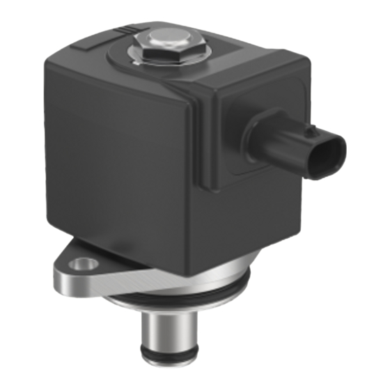
Type 6440 Electrical connection Automotive plugs for IP6K9K coil variants For mobile applications, coils are provided with the following automotive plugs: Plug KOSTAL MLK1.2, 2-pin, coding A (male) Plug TE MCON 1.2, 2-pin, coding A (male) Fig. 17: Automotive plugs for IP6K9K coil variants... -
Page 21: Faults
Type 6440 Faults FAULTS DANGER! Risk of injury from high pressure and discharge of medium. Before working on the device or system, switch off the pressure. Vent or drain lines. WARNING! Risk of injury from electric shock. Switch off the power supply before working on the device or system. Secure it against reactivation. -
Page 22: Logistics
Type 6440 Logistics LOGISTICS Transport and storage Protect the device against moisture and dirt in the original packaging during transportation and storage. Avoid UV radiation and direct sunlight. Protect connections from damage with protective caps. Observe permitted storage temperature. Disposal Environmentally friendly disposal Follow national regulations regarding disposal and the environment.
Need help?
Do you have a question about the 6440 and is the answer not in the manual?
Questions and answers