Table of Contents
Advertisement
Available languages
Available languages
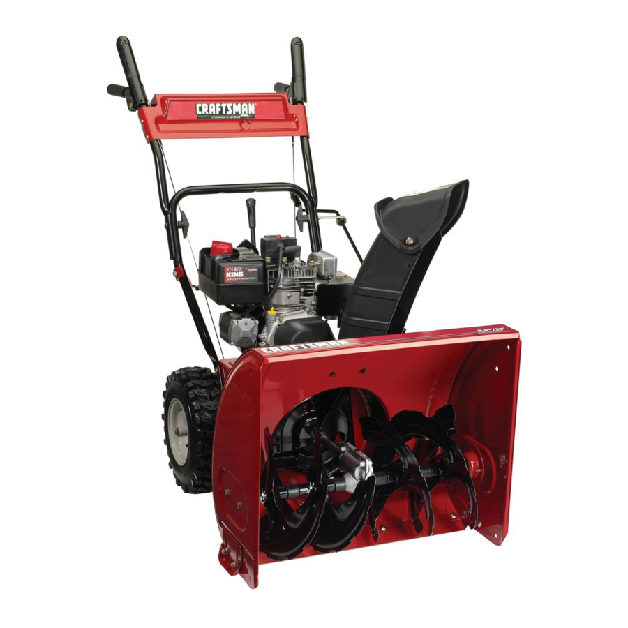
Operator's Manual
24" SNOW THROWER
Model No. 247.883550
CAUTION: Before using
this product, read this
manual and follow all
safety rules and operating
instructions.
Sears, Roebuck and Co., Hoffman Estates, IL 60179, U.S.A.
®
Visit our website: www.craftsman.com
• SAFETY
• ASSEMBLY
• OPERATION
• MAINTENANCE
• PARTS LIST
• ESPAÑOL
FORM NO. 769-01888D
7/19/2007
Advertisement
Chapters
Table of Contents

Related Manuals for Craftsman 247.88355


Summary of Contents for Craftsman 247.88355
- Page 1 Sears, Roebuck and Co., Hoffman Estates, IL 60179, U.S.A. ® Visit our website: www.craftsman.com • SAFETY • ASSEMBLY • OPERATION • MAINTENANCE • PARTS LIST • ESPAÑOL FORM NO.
-
Page 2: Table Of Contents
Operation ......Pages 12-15 Two -Year Warranty on Craftsman Snow Thrower This equipment is covered by a two-year warranty, provided that it is maintained, lubricated, and tuned up according to the instructions in the operator’s manual. -
Page 3: Repair Protection Agreement
REPAIR PROTECTION AGREEMENT Congratulations on making a smart purchase. Your new Craftsman® product is designed and manufactured for years of dependable opera- tion. But like all products, it may require repair from time to time. That’s when having a Repair Protection Agreement can save you money and aggravation. -
Page 4: Safety Instructions
WARNING This symbol points out important safety instructions which, if not followed, could endanger the personal safety and/or property of yourself and others. Read and follow all instructions in this manual before attempting to operate this machine. Failure to comply with these instructions may result in personal injury. -
Page 5: Maintenance And Storage
OPERATION • Do not put hands or feet near rotating parts, in the auger/impeller housing or chute assembly. Contact with the rotating parts can amputate hands and feet. • The auger/impeller control lever is a safety device. Never bypass its operation. - Page 6 This page left intentionally blank.
-
Page 7: Safety Labels
SAFETY LABELS DANGER KEEP AWAY FROM ROTATING IMPELLER AND AUGER. CONTACT WITH IMPELLER OR AUGER CAN AMPUTATE HANDS AND FEET. USE CLEAN-OUT TOOL TO UNCLOG DISCHARGE CHUTE. DISENGAGE CLUTCH LEVERS, STOP ENGINE , AND REMAIN BEHIND HANDLES UNTIL ALL MOVING PARTS HAVE STOPPED BEFORE UNCLOGGING OR SERVICING MACHINE. -
Page 8: Removing From Carton
NOTE: References to right or left side of the snow thrower are determined from behind the unit in the operating position (standing directly behind the snow thrower, facing the handle panel). REMOVING FROM CARTON Cut the corners of the carton and lay the sides flat on the ground. Remove and discard all packing inserts. - Page 9 Position the chute assembly over the base. See Figure 3. Close the flange keepers to secure the chute assembly to the chute base. See Figure 4. The flange keepers will click into place when properly secure. NOTE: If the flange keepers will not easily click into place, use the palm of your hand to apply swift, firm pressure to the back of each.
-
Page 10: Chute Clean-Out Tool
SET-UP Chute Clean-Out Tool A chute clean-out tool is fastened to the top of the auger housing with a mounting clip. See Figure 6. The tool is designed to clear a chute assembly of ice and snow. This item is fastened with a cable tie at the factory. -
Page 11: Assembly
Chute Assembly The distance snow is thrown can be adjusted by changing the angle of the chute assembly. To do so: Stop the engine by removing the ignition key and loosen the plastic wing knob found on the left side of the chute assembly. Pivot the chute upward or downward before retightening the wing knob. -
Page 12: Operation
Reverse Your snow thrower has two reverse (R) speeds. One (1) is the slower and two (2) is the faster. Craftsman Snow Throwers conform to the safety standard of the American National Standards Institute (ANSI). OPERATION Drive Control Shift Lever... -
Page 13: Chute Assembly
THROTTLE CONTROL The throttle control is located on the rear of the engine. It regulates the speed of the engine and will shut off the engine when moved into the STOP position. RECOIL STARTER HANDLE This handle is used to manually start the engine. ELECTRIC STARTER BUTTON Pressing the electric starter button engages the engine’s electric starter when plugged into a 120V power source. -
Page 14: Starting The Engine
CLEAN-OUT TOOL WARNING Never use your hands to clear a clogged chute assembly. Shut off engine and remain behind handles until all moving parts have stopped before using the clean-out tool to clear the chute assembly. The chute clean-out tool is conveniently fastened to the rear of the auger housing with a mounting clip. -
Page 15: To Engage Augers
Once the engine starts, release starter button. As the engine warms, slowly rotate choke control to the OFF position. If the engine falters, quickly rotate choke control back to FULL then slowly into the OFF position again. When disconnecting the extension cord, always unplug the end at the three-prong wall outlet before unplugging the opposite end from the snow thrower. -
Page 16: Checking/Changing Engine Oil
SERVICE AND MAINTENANCE ENGINE MAINTENANCE WARNING Before lubricating, repairing, or inspecting, disengage all controls and stop engine. Wait until all moving parts have come to a complete stop. Checking Engine Oil Be sure engine is upright and level. Unscrew oil fill cap from oil filler tube and wipe dipstick clean. Screw oil fill cap back into oil filler tube. -
Page 17: Engine Speed
Checking Spark Plug Check spark plug yearly or every 100 operating hours Clean area around spark plug. Remove and inspect spark plug. Replace spark plug if porcelain is cracked or if electrodes are pitted, burned or fouled with deposits Check electrode gap with a feeler gauge and set gap to .030 (0.76mm) if necessary. -
Page 18: Drive Control
SERVICE AND MAINTENANCE SHAVE PLATE AND SKID SHOES The shave plate and skid shoes on the bottom of the snow thrower are subject to wear. They should be checked periodically and replaced when necessary. To remove skid shoes: Remove the four carriage bolts and hex flange nuts which secure them to the snow thrower. -
Page 19: Belt Replacement
SERVICE AND MAINTENANCE Chute Bracket If the spiral at the bottom of the chute directional control is not fully engaging with the chute assembly, the chute bracket can be adjusted. To do so: Loosen the two nuts which secure the chute bracket and reposi- tion it slightly. -
Page 20: Drive Belt
SERVICE AND MAINTENANCE Remove the frame cover from the underside of the snow thrower by removing four self-tapping screws which secure it. See Figure Remove the belt as follows. Refer to Figure 23. Loosen and remove the shoulder screw which acts as a belt keeper. -
Page 21: Friction Wheel Removal
Remove the belt as follows. Refer to Figure 25. Roll the auger belt off the engine pulley. Use a wrench to pivot the idler pulley toward the right. Lift the drive belt off engine pulley. Carefully pivot the snow thrower up and forward so that it rests on the auger housing. - Page 22 Carefully remove the hex nut and washer which secures the hex shaft to the snow thrower frame and lightly tap the shaft’s end to dislodge the ball bearing from the right side of the frame. See Figure 28. NOTE: Be careful not to damage the threads on the shaft. Carefully position the hex shaft downward and to the left before carefully sliding the friction wheel assembly off the shaft.
-
Page 23: Maintenance Schedule
SERVICE AND MAINTENANCE WARNING Before performing any type of maintenance/service, disengage all controls and stop the engine. Wait until all moving parts have come to a complete stop. Disconnect spark plug wire and ground it against the engine to prevent unintended starting. Always wear safety glasses during operation or while performing any adjustments or repairs. -
Page 24: Preparing Engine/Snow Thrower
If the snow thrower will not be used for 30 days or longer, or if it is the end of the snow season when the last possibility of snow is gone, the equipment needs to be stored properly. Follow storage instructions below to ensure top performance from the snow thrower for many more years. PREPARING ENGINE Short-Term Storage It is important to prevent gum deposits from forming in essential fuel... -
Page 25: Troubleshooting
Before performing any type of maintenance/service, disengage all controls and stop the engine. Wait until all moving parts have come to a complete stop. Disconnect spark plug wire and ground it against the engine to prevent unintended starting. Always wear safety glasses during operation or while performing any adjustments or repairs. -
Page 26: Parts List
Craftsman Snow Thrower Model 247.883550 9 19 PARTS LIST... - Page 27 Craftsman Snow Thrower Model 247.883550 Ref. No. Part No. 731-2635 Snow Removal Tool Mount 684-04057A Impeller Assembly, 12” Dia. 710-0347 Hex Screw, 3/8-16, 1.75, Gr5 710-0451 Bolt, Carriage, 5/16-18, .750 Gr1 710-04484 Screw, 5/16-18, 0.750 710-0703 Screw, Carriage, 1/4-20, .750, Gr5...
- Page 28 PARTS LIST Craftsman Snow Thrower Model 247.883550...
- Page 29 Craftsman Snow Thrower Model 247.883550 Ref. No. Part No. 631-04133A Handle Ass’y, Lock LH 631-04134B Handle Ass’y, Lock, RH 684-04105B Handle Ass’y, Engagement LH 684-04106B Handle Ass’y, Engagement, RH 710-0376 Screw, Self-tapping, 5/16-18, .625 710-04484 Screw, Self-tapping, 5/16-18, .750 710-0606 Screw, Self-tapping, 1/4-20, 1.50...
- Page 30 Craftsman Snow Thrower Model 247.883550 PARTS LIST 24 30 26 13...
- Page 31 Craftsman Snow Thrower Model 247.883550 Ref. No. Part No. 656-04025A Disc Assembly, Friction Wheel 684-04153 Friction Wheel Assembly, 5.5 OD 684-04154 Support Bracket, Friction Wheel 684-04156A Shift Assembly, Rod 710-0627 Hex Screw, 5/16-24, .750, Gr5 710-0788 Screw, 1/4-20, 1.000 710-1652 Screw, 1/4-20 x .625...
- Page 32 PARTS LIST Craftsman Engine Model LH195SP-67514 For Snow Thrower Model 247.883550...
- Page 33 Craftsman Engine Model LH195SP-67514 For Snow Thrower Model 247.883550 Ref. No. Part No. 36469A Cylinder (Incl. 2,20,72 & 125) 26727 Dowel Pin 30969 Extension Cap (1/4-18 NPT) 28277 Washer 31334 Governor Rod 37729 Governor Lever 31335 Governor Lever Clamp 651018 Screw, T-15, 8-32 x 19/64”...
- Page 34 Craftsman Engine Model LH195SP-67514 For Snow Thrower Model 247.883550 Ref. No. Part No. 650664 Screw, 1/4-20 x 1-19/32” 33673A *Intake Pipe Gasket 36701 Compression Release Weight 36702 Compression Release Spring 35656A Blower Housing 650737 Screw, 1/4-20 x 1/2” 34212 Hold Down Bracket 30200 Screw, 10-24 x 9/16”...
-
Page 35: Parts List
Craftsman Engine Model LH195SP-67514 For Snow Thrower Model 247.883550 Ref. No. Part No. 590707 Recoil Starter 590599A Spring Pin (Incl. 4) 590600 Washer 590696 Retainer 590601 Washer 590697 Brake Spring 590698 Starter Dog 590699 Dog Spring 590709 Pulley & Rewind Spring Ass’y. - Page 36 Sears, Roebuck and Co., U.S.A. (Sears), the California Air Resources Board (CARB) and the United States Environmental Protection Agency (U.S. EPA) Emission Control System Warranty Statement (Owner’s Defect Warranty Rights and Obligations) EMISSION CONTROL WARRANTY COVERAGE IS APPLICABLE TO CERTI- FIED ENGINES PURCHASED IN CALIFORNIA IN 1995 AND THEREAF- TER, WHICH ARE USED IN CALIFORNIA, AND TO CERTIFIED MODEL California and United States Emission Control Defects Warranty Statement...
- Page 37 Look For Relevant Emissions Durability Period and Air Index Information On Your Engine Emissions Label Engines that are certified to meet the California Air Resources Board (CARB) Tier 2 Emission Standards must display information regarding the Emissions Durability Period and the Air Index. Sears, Roebuck and Co., U.S.A. makes this information available to the consumer on our emission labels.
-
Page 38: Español
Servicio y Mantenimiento ...Página 50 DECLARACIÓN DE GARANTÍA Garantía de dos años para la máquina quitanieve Craftsman Este equipo está cubierto por una garantía de dos años, siempre que se mantenga, lubrique y ajuste de acuerdo con las instrucciones del presente manual del operador. -
Page 39: Acuerdo De Protección Para Reparaciones
ACUERDO DE PROTECCIÓN PARA REPARACIONES Felicitaciones por haber realizado una adquisición inteligente. El producto Craftsman® que ha adquirido está diseñado y fabricado para brindar muchos años de funcionamiento confiable. Pero como todos los productos a veces puede requerir de reparaciones. Es en ese momento cuando el disponer de un Acuerdo de protección para... -
Page 40: Prácticas Operación Seguras
INSTRUCCIONES DE SEGURIDAD ADVERTENCIA La presencia de este símbolo indica que se trata de instrucciones importantes de seguridad que se deben respetar para evitar poner en peligro su seguridad personal y/o material y la de otras personas. Lea y siga todas las instrucciones de este manual antes de poner en funcionamiento esta máquina. -
Page 41: Instrucciones De Seguridad
INSTRUCCIONES DE SEGURIDAD OPERACIÓN • No ponga las manos o los pies cerca de las piezas rotatorias, en la caja de la barrena / motor o en el montaje del canal de descarga. El contacto con las piezas rotatorias puede producir la amputación de manos y pies. •... -
Page 42: Montaje
NOTA: las referencias al lado derecho o y ciertos de la máquina quitanieve se determinan desde la parte posterior de la unidad en posición de operación (permaneciendo directamente detrás de la máquina quitanieve, mirando hacia el panel de la manija). EXTRACCIÓN DE LA UNIDAD DE LA CAJA Corte las esquinas de la caja de cartón y extiéndala en el piso Quite y descarte todos los insertos de empaque. - Page 43 Sitúe el montaje del canal sobre la base. Vea la figura 3. Cierre los fijadores de la brida para asegurar el montaje del canal a la base del canal. Vea la figura 4. Los fijadores de la brida emiten un chasquido cuando están bien asegurados. NOTA: si los fijadores de la brida no se ajustan en su lugar fácilmente, utilice la palma de su mano para aplicar una presión rápida y firme en la parte posterior de cada uno.
- Page 44 CONFIGURACIÓN Herramienta de Limpieza del Canal Hay una herramienta de limpieza del canal iajustada a la parte superior de la caja de la barrena con un pasador de ensamblado. Vea la figura 6. La herramienta está diseñada para limpiar el hielo y la nieve del montaje de un canal.
- Page 45 Ajuste del montaje del canal Es posible ajustar la distancia a la cual se arroja la nieve cambiando el ángulo del montaje del canal. Para hacerlo: Detenga el motor quitando la llave de encendido y afloje la perilla a mariposa de plástico que se encuentra en el lado izquierdo del montaje del canal.
-
Page 46: Operación
Hay dos velocidades de retroceso (R). La uno (1) es la más lenta, y la dos (2) es la más rápida. Cumple con los estándares de seguridad de ANSI Las máquinas quitanieve de Craftsman cumplen con los estándares de seguridad del instituto estadounidense de estándares nacionales (ANSI). OPERACIÓN Palanca... - Page 47 CONTROL DEL ESTRANGULADOR El control del estrangulador está ubicado en el motor. Regula la velocidad del motor, y lo apaga cuando mueva el control a la posición STOP. MANIJA DEL ARRANCADOR DE RETROCESO Esta manija se utiliza para arrancar el motor manualmente. BOTÓN DEL ARRANCADOR ELÉCTRICO Si oprime el botón del arrancador eléctrico se engrana el...
-
Page 48: Antes De Encender El Motor
HERRAMIENTA DE LIMPIEZA ADVERTENCIA Nunca use sus manos para liberar un montaje de canal tapado. Antes de destaparlo, apague el motor y permanezca detrás de las manijas hasta que todas las partes móviles se hayan detenido. La herramienta de limpieza del canal está ajustada convenientemente a la parte posterior de la caja de la barrena con un pasador de ensam- blado. -
Page 49: Detención Del Motor
NOTA: si el motor ya está caliente, ubique el control del obturador en posición OFF en lugar de FULL Presione el cebador dos o tres veces para arrancar el motor en frío, asegurándose de cubrir el orificio de ventilación situado en el centro del cebador cuando esté... -
Page 50: Mantenimiento De Motor
SERVICIO Y MANTENIMIENTO ADVERTENCIA Antes de realizar tareas de lubricación, reparación o inspección, desengrane todos los controles y detenga el motor. Espere a que se detengan todas las piezas móviles. MANTENIMIENTO DE MOTOR Control del aceite del motor Asegúrese de que el motor está vertical y nivelado. Desenrosque el tapón de llenado de aceite del tubo de llenado de aceite y limpie la varilla de nivel de aceite. - Page 51 SERVICIO Y MANTENIMIENTO Control de la bujía Controle la bujía anualmente o cada 100 horas de operación. Limpie el área alrededor de la bujía. Saque e inspeccione la bujía. Cambie la bujía si la porcelana está rota o si los electrodos están: picados, quemados o atorados con depósitos Controle el espacio del electrodo con un calibrador de sepa- raciones y ajuste dicho espacio a 0,030 pulg (0,76 mm) si es...
- Page 52 SERVICIO Y MANTENIMIENTO Eje de la barrena Al menos una vez por temporada, quite los pasadores de cuchilla del eje de la barrena. Rocíe lubricante al interior del eje, alrededor de los separadores. Asimismo, lubrique los cojinetes bridados que se encuentran en ambos extremos del eje.
-
Page 53: Reemplazo De La Correa
SERVICIO Y MANTENIMIENTO Soporte del canal Si la espiral situada en la parte inferior del control direccional del canal no se engancha completamente con el montaje del canal, es posible ajustar el soporte del canal. Para hacerlo: Afloje las dos tuercas que sujetan el soporte del canal y cambie su posición ligeramente. - Page 54 SERVICIO Y MANTENIMIENTO Saque la cubierta del marco desde debajo de la máquina quitanieve retirando los cuatro tornillos autorroscantes que la aseguran. Vea la figura 21. Afloje y retire el tornillo con reborde que actúa como guarda de la correa. Vea la figura 22. Desenganche el resorte de la ménsula de soporte del marco.
- Page 55 SERVICIO Y MANTENIMIENTO Saque la correa de la barrena de la polea del motor. Tome la polea loca y gírela hacia la derecha. Vea la figura Levante la correa de la barrena para sacarla de la polea del motor. 4. Gire con cuidado la máquina quitanieve hacia arriba y hacia delante de manera que quede apoyada sobre la caja de la barrena.
- Page 56 SERVICIO Y MANTENIMIENTO Retire con cuidado la tuerca hexagonal y la arandela que sujetan el eje hexagonal al marco de la máquina quitanieve, y golpee suavemente el extremo del eje para desplazar el cojinete de bolas del lado derecho del marco. Vea la figura 27. NOTA: Tenga cuidado de no dañar las roscas del eje.
- Page 57 SERVICIO Y MANTENIMIENTO BARRENAS Las barrenas están ajustadas al eje espiral con dos pasadores de cuchilla y pasadores de chaveta. Si la barrena golpea un objeto extraño o una barra de hielo, la máquina quitanieve está diseñada de manera que los pasadores se pueden cortar. Si las barrenas no giran, verifique si los pasadores se cortaron.
-
Page 58: Almacenamiento Fuera De Temporada
ALMACENAMIENTO FUERA DE TEMPORADA Si no se va a utiliza el equipo durante 30 días o más, o si es el final de la temporada de nieve y ya no existe posibilidad de que nieve, es necesario almacenar el equipo de manera adecuada. Siga las instrucciones de almacenamiento que se indican a continuación para garantizar el rendimiento máximo de la máquina quitanieve durante muchos años . -
Page 59: Solución De Problemas
Antes de realizar cualquier tipo del mantenimiento/servicio, suelte todos los mandos y pare el motor. Espere hasta que todas las partes de movimiento hayan venido a una parada completa. Desconecte el alambre de bujía y báselo contra el motor para prevenir el comienzo involun- tario. - Page 60 Sears, Roebuck and Co., U.S.A. (Sears), el Consejo de Recursos Ambientales de California (CARB) y la Agencia de Protección Ambiental de los Estados Unidos (EPA) Declaración de garantía del sistema de control de emisiones (derechos y obligaciones de la garantía de defectos del propi- LA COBERTURA DE LA GARANTÍA DE CONTROL DE EMISIONES ES APLICABLE A LOS MOTORES CERTIFICADOS COMPRADOS EN CALIFOR- NIA EN 1995 Y POSTERIORMENTE, QUE SE UTILIZAN EN CALIFORNIA,...
- Page 61 Busque el período de duración de emisiones importantes yla información de clasificación de aire en la etiqueta de emisiones de su motor Los motores cuyo cumplimiento con los estándares de emisión Tier 2 de la Comisión de Recursos Ambientales de California (CARB) esté...
- Page 62 NOTAS...
- Page 63 NOTAS...
- Page 64 Get it fixed, at your home or ours! For repair – in your home – of all major brand appliances, lawn and garden equipment, or heating and cooling systems, no matter who made it, no matter who sold it! For the replacement parts, accessories and owner’s manuals that you need to do-it-yourself.
Need help?
Do you have a question about the 247.88355 and is the answer not in the manual?
Questions and answers