Toa VS-900MF Installation Manual
Voice security system
Hide thumbs
Also See for VS-900MF:
- Software setup manual (52 pages) ,
- Application note (2 pages) ,
- Specifications (1 page)
Table of Contents
Advertisement
Quick Links
VOICE SECURITY SYSTEM
Be sure to leave system installations, adjustments, and data settings to the dealer from whom
you have purchased.
Please follow the instructions in this manual to obtain the optimum results from this unit.
We also recommend that you keep this manual handy for future reference.
INSTALLATION MANUAL
VS-900
Advertisement
Table of Contents

Related Manuals for Toa VS-900MF


Summary of Contents for Toa VS-900MF
- Page 1 VOICE SECURITY SYSTEM Be sure to leave system installations, adjustments, and data settings to the dealer from whom you have purchased. Please follow the instructions in this manual to obtain the optimum results from this unit. We also recommend that you keep this manual handy for future reference. INSTALLATION MANUAL VS-900...
-
Page 2: Table Of Contents
6. INSTALLATION PRECAUTIONS 7. SYSTEM CONFIGURATION AND EQUIPMENT FUNCTIONS 7.1. System Configuration ... 9 7.2. Equipment Functions ... 10 8. VS-900MF MAIN FRAME NOMENCLATURE AND FUNCTIONS 9. INSTALLATION AND CONNECTION PROCEDURES 10. EQUIPMENT INSTALLATION 10.1. VS-900MF Main Frame 10.1.1. Rack mounting ... 14 10.1.2. - Page 3 12.11.4. Connecting the VS-900SC to another VS-900SC unit ... 46 12.11.5. Connection to an optical/audio signal converter ... 46 12.12. VS-900MF Main Frame and PU-200 Power Transformer Connection ... 47 13. MAIN FRAME AND PC CONNECTION 13.1. Programming PC Connection 13.1.1.
-
Page 4: Safety Precautions
AC outlet and contact your nearest TOA dealer. Make no further attempt to operate the unit in this condition as this may cause fire or electric shock. - Page 5 • Contact your TOA dealer as to the cleaning. If dust is allowed to accumulate in the unit over a long period of time, a fire or damage to the unit may...
-
Page 6: Fcc Requirements
(7) If trouble is experienced with this equipment VS-900, please contact TOA Electronics, Inc., 601 Gateway Boulevard, Suite 300, South San Francisco, CA. 94080, phone (800) 733-4748 for repair and warranty information. -
Page 7: Industrial Canada Requirements
3. INDUSTRIAL CANADA REQUIREMENTS EQUIPMENT ATTACHMENT LIMITATIONS "NOTICE: The Industry Canada label identifies certified equipment. This certification means that the equipment meets telecommunications network protective, operational and safety requirements as prescribed in the appropriate Terminal Equipment Technical Requirements document(s). The Department does not guarantee the equipment will operate to the user's satisfaction. -
Page 8: General Description
4. GENERAL DESCRIPTION The VS-900 Security System is a voice communication system that permits calls to be quickly and easily made - even in emergency situations - with the touch of single button. The system can record conversations, and features external equipment sync output and operation log output. These features combine to make the VS-900 an ideal system for voice security applications. -
Page 9: System Configuration And Equipment Functions
7. SYSTEM CONFIGURATION AND EQUIPMENT FUNCTIONS 7.1. System Configuration VS-900 Exchange (1) Main Frame VS-900MF/ Main Frame Mounting Bracket YC-303 Master Station Rack Mount Panel Interface Card PN-100B VS-900MS (1) Power Transformer Telephone Interface Uint PU-200 Card VS-900AL (2) Power Transformer... -
Page 10: Equipment Functions
7.2. Equipment Functions • VS-900MF Main Frame The VS-900MF accommodates the following cards: Up to 2 VS-900MS or VS-900AL Cards (both cards may be mixed), up to 4 VS-900RS or VS-910RS Cards (both cards may be mixed), 1 VS-900CO Card, 1 VS- 900AF Card, and 1 VS-900TI Card. - Page 11 • RS-160 Half-duplex Remote Substation (Indoor Vandal-Resistant Type) The RS-160 can call and converse with the registered master stations. It utilizes a single-pair shielded cable. • RS-170 Half-duplex Remote Substation (Outdoor Vandal-Resistant Type) The RS-170 can call and make converse with the registered master stations. It utilizes a single-pair shielded cable.
-
Page 12: Vs-900Mf Main Frame Nomenclature And Functions
8. VS-900MF MAIN FRAME NOMENCLATURE AND FUNCTIONS 1. AC Input Connectors Connect to the AC output terminal of the PU-200 power transformer unit. (See p. 46.) 2. 24 V DC Input Connector Connects to a battery (24 V DC). (See p. 46.) 3. -
Page 13: Installation And Connection Procedures
Exchange/Station Configuration, Wiring Schedule and Station Numbering Schedule (2) Equipment Installation Installing the VS-900MF Main Frame in an Equipment Rack or on a Wall Installing the PU-200 Power Transformer in an Equipment Rack or on a Wall Installing the Remote Substation and the Option Handset... -
Page 14: Equipment Installation
10. EQUIPMENT INSTALLATION 10.1. VS-900MF Main Frame 10.1.1. Rack mounting Step 1. Attach the supplied rack mounting brackets to the frame. Mounting bracket (accessory) Step 2. Mount the frame to an equipment rack. Fiber washer (8 places) (accessory) Machine screw M4 x 10 (6 places) -
Page 15: Wall Mounting
10.1.2. Wall mounting (Optional YC-303 Wall Mounting Frame is required.) Step 1. Mount the YC-303 bracket to the wall. Wood screw M5.1 x 38 (accessory) Step 2. Remove the VS-900MF's front panel, then mount the VS-900MF on the YC-303. 78 78 78 Knockout (for wiring) 391.4... -
Page 16: Pu-200 Power Transformer Unit 10.2.1. Rack Mounting
10.2. PU-200 Power Transformer Unit 10.2.1. Rack mounting Step 1. Remove the 4 mounting screws, and attach the supplied wall mounting brackets to the transformer unit using the removed screws. Step 2. Attach the PU-200 to the PN-100B Rack Mount Panel. Flange nut M3 (supplied with the PN-100B) Step 3. -
Page 17: Wall Mounting
10.2.2. Wall mounting Step 1. Remove the 4 mounting screws, and attach the supplied wall mounting brackets to the transformer using the removed screws. Step 2. Fix the unit on the wall. Use the supplied wood screws (3.5 x 25) as appropriate for mounting. Wood screw M3.5 x 25 (accessory) Wall mounting bracket (accessory) -
Page 18: Rs-150, Rs-160, Rs-170, Rs-180 And Rs-190 Substations
10.3. RS-150, RS-160, RS-170, RS-180 and RS-190 Substations Mount the substation to an electrical box mounted in the wall. RS-150/-160/-170/-180/-190 Oval head combination screw M4 x 25 (accessory) Accessory screws The RS-150, RS-160, RS-170, RS-180 and RS-190 come with 2 types of screws: oval head combination screw M4 x 25 and oval head slotted screw UNC No.6 x 18. -
Page 19: Wall Mounting
10.4. RS-191 Option Handset (Indoor type) 10.4.1. Wall mounting Mount the option handset to an electrical box mounted in the wall. Oval head combination screw M4 x 25 (accessory) RS-191 10.4.2. RS-190 and RS-191 connection Plug out the jumper from the connector on the RS-190's side panel, then plug the RS-191's connection cable instead as illustrated below. -
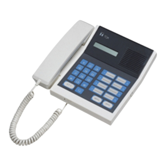
Page 20: Master Station
10.5. Master Station 10.5.1. Desk-top mounting Connect the supplied modular-plug cord. 10.5.2. Wall mounting Pull out, rotate, and reset the cradle hook, then mount the station on the wall using the supplied wall mounting frame. Use the supplied wood screws as appropriate. Remove the cradle hook. -
Page 21: Vs-900Sc Site Connector
10.6. VS-900SC Site Connector 10.6.1. Rack mounting 10.6.2. Mounting to the VS-900MF VS-900MF 10.6.3. Wall mounting * Use the supplied wood screws as appropriate. When using them, mount the unit to wooden walls stronger than plywood of over 12 mm in thickness. -
Page 22: Vs-900Mf Card Installation
Step 6. Reinstall the removed cards. Step 7. Switch the VS-900MF power on. Important Be sure to replace the battery while the VS-900MF power is on. Otherwise, stored time (clock) data will be lost. Danger of explosion if battery is incorrectly replaced. -
Page 23: Card Installation
11.2. Card Installation Step 1. Remove each card from its static-protective bag, and install it in its designated position in the Main Frame. • For the VS-900TI, perform exchange number setting BEFORE installation. Refer to p. 42 "Exchange Number Setting." Step 2. -
Page 24: Wiring
12. WIRING 12.1. Wiring from the Station or Outside Line Step 1. Remove the main frame's bottom panel as shown below. Step 2. Connect stations or outside lines to their respective cards as shown below. -
Page 25: Supplied Connector Connection
12.2. Supplied Connector Connection Use the supplied connectors for exchange connections as follows. Step 1. Insert a cable into the connector and tighten the screw. Step 2. After cable connection is completed, press the connector onto the circuit board's connector. -
Page 26: Installation Precaution
INSTALLATION PRECAUTION Before mounting this unit to the VS-900MF Main Frame, be sure to set the DIP switch SW1 on the circuit board according to the conditions of use as shown in the table below. Note: The previous VS-900MS does not employ the DIP switch. -
Page 27: Master Station And Vs-900Ms Connection, Ms Addressing
12.3.1. Master Station and VS-900MS connection • The VS-900MS can be interfaced with up to 2 MS-900 master stations. • Because up to 2 VS-900MS cards can be mounted in the VS-900MF Main Frame, up to four master stations can be connected per frame. - Page 28 [Connection] • Connect the MS-900 to the VS-900MS using 2 twisted pair cables as shown below referring to the following procedures. 1. Fit the 4P connector (supplied with the VS-900MS) to one cable end, and a 6-position 4-contact modular jack (prepare locally) to the other cable end. 2.
-
Page 29: External Recording Device And Vs-900Ms Connection
12.3.2. External recording device and VS-900MS connection An external recording device can be connected to each master station line. [Connection] To connect the external recording device, use a twisted pair cable for audio output, and a twisted pair cable for control output. The audio output is 0 dB* and of unbalanced type. The control output is an open collector output 20 mA, 24 V DC max. -
Page 30: External Speaker Connection
12.4. MS-900 Master Station Connection and Adjustment 12.4.1. External speaker connection Follow the procedures below when connecting an external speaker (8 Ω). Step 1. Remove the MS-900's rear terminal cover and set the internal slide switch to the [EXT. SP] position. Internal/External speaker selection switch Terminal cover EXT.SP terminal... -
Page 31: Vs-900Al Telephone Interface Card Connection
12.5. VS-900AL Telephone Interface Card Connection 12.5.1. Telephone and VS-900AL connection The VS-900AL can be interfaced with up to 2 commercial telephone sets. Use the telephone which complies with the FCC Regulation Part 68. [Connection] To connect the telephone set to the VS-900AL, use a twisted pair cable. The connector of the cable end going to the telephone needs to be the type that can be connected to the telephone connector. - Page 32 [Setting telephone's talking volume levels] When the talking volume is low, set it using the switch SW101 (for Line 1) or SW201 (for Line 2) on the VS- 900AL card as illustrated below. Setting of telephone volume switches on the VS-900AL card VS-900AL SW101 D110...
-
Page 33: External Recording Device And Vs-900Al Connection
12.5.2. External recording device and VS-900AL connection An external recording device can be connected to each telephone line. [Connection] To connect the external recording device, use a twisted pair cable for audio output, and a twisted pair cable for control output. The audio output is 0 dB* and of unbalanced type. The control output is an open collector output of 20 mA, 24 V DC max. -
Page 34: Substation And Vs-900Rs Connection
12.6. VS-900RS Remote Sub-station Interface Card Connection 12.6.1. Substation and VS-900RS connection The VS-900RS can be interfaced with up to 16 substations. [Connection] Use a (STP) shielded, twisted pair cable to connect the sub-station to the VS-900RS. Refer to the following table for the maximum recommended cable length between the two. -
Page 35: External Amplifier And Vs-900Rs Connection
Electrical characteristics of the CN5 connector Voice output: Unbalanced, –20 dB* Voice input: Balanced, acceptable signals on the 25 V line output from a paging amplifier Rated at over 16 W power output (ex. TOA BG-130 30 W amplifier) 0 dB = 1 V VS-900RS... -
Page 36: Vs-910Rs Substation Interface Card Connection
12.7. VS-910RS Substation Interface Card Connection RS-190 Substation and VS-910RS connection The VS-910RS can be interfaced with up to 16 RS-190 Substations. [Connection] Use 2 pairs of twisted cables to connect the RS-190 and the VS-910RS. Refer to the following table for the maximum recommended cable length between the two. -
Page 37: Vs-900Co Outside Line Interface Card Connection
Install a protector if not yet installed by the telephone company. This terminal must be installed by the telephone company. Note: Paging from the Outside Line(s) is not supported. Custom firmware for the VS-900MF must be obtained from TOA to support this special functionality. -
Page 38: External Recording Device And Vs-900Co Connection
12.8.2. External recording device and VS-900CO connection An external recording device can be connected to each telephone line. [Connection] To connect the external recording device, use a twisted pair cable for audio output, and a twisted pair cable for control output. The audio output is 0 dB* and of unbalanced type. The control output is an open collector output o f 20 mA, 24 V DC max. -
Page 39: Vs-900Af Audio Function Card Connection
12.9. VS-900AF Audio Function Card Connection 12.9.1. Amplifier and VS-900AF connection Paging can be provided through connected external amplifiers using the VS-900AF. [Connection] To connect the amplifier to the VS-900AF, use a twisted pair cable for audio output, and a twisted pair cable for control output. -
Page 40: External Sound Source And Vs-900Af Connection
12.9.2. External sound source and VS-900AF connection The External Sound Source Distribution function can be operated using the VS-900AF. [Connection] To connect external sound sources to the VS-900AF, use a twisted pair cable for audio input, and a twisted pair cable for control input (level-operated activation). The audio input is 0 dB* and of unbalanced type. The control start input is a no-voltage make contact of 20 mA, 24 V DC max. -
Page 41: Vs-900Ti Tie-Line Interface Card Exchange Interconnection
12.10. VS-900TI Tie-Line Interface Card Exchange Interconnection Up to 16 exchanges can be tie-line interconnected using the VS-900TI card. [Connection] To interconnect the exchanges, use 2 twisted pair cables for voice tie-lines (CN1, CN2, CN3 & CN4), and an (STP) shielded, twisted pair cable for data lines (CN6). A maximum of 4 audio tie-lines can be connected. Refer to the following table for the maximum recommended length for each cable type between exchanges. - Page 42 Connect as shown below. Exchange interconnection by means of VS-900TI Shielded, twisted pair cable Shielded, twisted pair cable VS-900TI 2 twisted pair cables 2 twisted pair cables 2 twisted pair cables 2 twisted pair cables VS-900TI 2 twisted pair cables 2 twisted pair cables 2 twisted pair cables 2 twisted pair cables...
- Page 43 [Exchange Number Setting] When interconnecting the exchanges using the VS-900TI, assign the exchange number to each exchange with the SW1 switch located on the VS-900TI's circuit board. (Refer to the table below.) Exchange No. setting VS-900TI Initial status: Exchange No. 1 1 2 3 4 5 6 7 8 Exchange No.
-
Page 44: Vs-900Sc Site Connector Connection
Fiber optic cable VS-900TI Tie-Line unit O.A.L. O.D.L. VS-900MF Audio signal line * O.A.L. (Optical Analog Link): Optical/audio signal converter O.D.L. (Optical Data Link): • For the optical/audio signal converter, prepare one which can transmit a 600 Ω, 0 dBm signal. -
Page 45: Connection To The Vs-900Ti
12.11.3. VS-900SC connection to the VS-900TI Connect each connector of the unit's Voice Lines 1 – 4 to the corresponding connector on the VS-900TI's CN 1 – 4. Pins No. 1 and 2 of each connector of Voice Lines 1 – 4 are for receiving ends, while pins No. 3 and 4 are for transmitting ends. -
Page 46: Connecting The Vs-900Sc To Another Vs-900Sc Unit
12.11.4. Connecting the VS-900SC to another VS-900SC unit Connect individual Voice Lines 1 – 4 connectors to each other. Pins No. 1 and 2 of each connector of Voice Lines 1 – 4 are for receiving ends, while pins No. 3 and 4 are for transmitting ends. -
Page 47: Vs-900Mf Main Frame And Pu-200 Power Transformer Connection
Connect as shown below using 2 parallel pair cables. Use cables with a sufficient current capacity and a heavier gauge than AWG18. Two PU-200 units are required when using 3 or 4 VS-900RS cards. Connect the backup power supply, if needed, to the VS-900MF's DC input as illustrated. VS-900MF and power supply connection OUTPUT 20V AC 2.5A... -
Page 48: Main Frame And Pc Connection
13. MAIN FRAME AND PC CONNECTION 13.1. Programming PC Connection 13.1.1. Direct connection by means of RS-232C Using the RS-232C cable, connect the programming PC to the VS-900MF Main Frame as shown below. Direct connection by means of RS-232C (Programming PC) CN106... -
Page 49: Connection Via Modem
13.1.2. Connection via modem Connect as shown below. Connection via modem (Programming PC) CN106 CN108 Front view Main Frame VS-900MF RS-232C cross cable VS-900MF RS-232C cross cable Modem Modem... -
Page 50: Operation Log Pc Connection
13.2. Operation Log PC Connection 13.2.1. Direct connection by means of RS-232C Using the RS-232C cable, connect the operating log PC to the VS-900MF as shown below. Direct connection by means of RS-232C (Operation log PC) CN106 CN108 Front view... -
Page 51: Connection Via Modem
CN106 CN108 Front view Main Frame VS-900MF 13.3. System Programming Use the supplied PC software to perform such system programming as: system clock time, station number and function settings. For its use and installation, refer to the "VS-900 Setup Software Instruction Manual."... -
Page 52: Speech And Function Tests
14. SPEECH AND FUNCTION TESTS Using installed equipment, perform both speech and function tests after system programming completion. 14.1. Speech Test (1) Calls from the substation • Call the Master Station (telephone) from each substation to check to be sure that a conversation is possible. Also, check to confirm that the master station (telephone) registered in system programming is correctly called. -
Page 53: Specifications
15. SPECIFICATIONS [VS-900MF Main Frame] Power Source Current Consumption Speech Path Configuration Serial port Installation Method Other Connection Terminal Operating Temperature Finish Dimensions Weight Note: The design and specifications are subject to change without notice for improvement. • Accessories Rack mounting bracket ... 2 Machine screw (M4 x 10) ... -
Page 54: Vs-900Al Telephone Interface Card
[VS-900AL Telephone Interface Card] Power Source Current Consumption Supply Power Number of Lines Conversation Recording Output Selectable Signal Type Monitoring Function Applicable Terminal Control Function Connection Terminal Operating Temperature Weight * 0 dB = 1 V Note: The design and specifications are subject to change without notice for improvement. •... -
Page 55: Vs-910Rs Substation Interface Card
[VS-910RS Remote Sub-station Interface Card] Power Source Current Consumption Number of Lines Number of Links Conversation Method Audio Output Supply Power Control System Connection Terminal Connection Monitoring Function Operating Temperature Weight * 0 dB = 1 V Note: The design and specifications are subject to change without notice for improvement. •... -
Page 56: Vs-900Af Audio Function Card
[VS-900AF Audio Function Card] Power Source Current Consumption Paging Output External Source Distribution Conference Link Connection Terminal Operating Temperature Weight * 0 dB = 1 V Note: The design and specifications are subject to change without notice for improvement. • Accessories 2-pin dedicated connector ... -
Page 57: Vs-900Sc Site Connector
[VS-900SC Site Connector] Power Source Name of Links Input Output Installation Method Connection Terminal Operating Temperature Finish Dimensions Weight * 0 dB = 0.775 V Note: The design and specifications are subject to change without notice for improvement. • Accessories Rack-mounting bracket ...
Need help?
Do you have a question about the VS-900MF and is the answer not in the manual?
Questions and answers