Advertisement
WC2800##
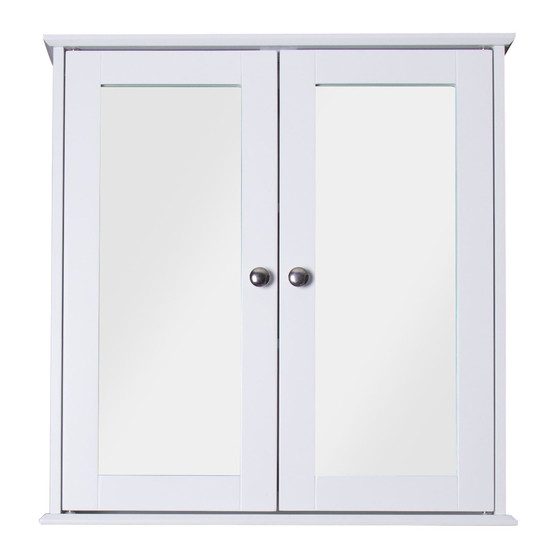
ASHBY 2 DOOR CABINET
CONTACT DETAILS
Croydex
Central Way
Andover
Hampshire
SP10 5AW
UK
Tel: +44 (0)1264 365881
Email: info@croydex.co.uk
www.croydex.com
A A A
PRODUCT DIMENSIONS (SEE ABOVE)
A - 560MM
B - 130MM
C - 580MM
ALL ILLUSTRATIONS OF THE PRODUCT ARE FOR
REFERENCE ONLY. COMPONENTS SUPPLIED WITH
INDIVIDUAL PRODUCTS MAY DIFFER
ALL PRODUCT DIMENSIONS DETAILED IN THIS
INSTALLATION AND MAINTENANCE MANUAL ARE
APPROXIMATE
1
C
B
CAB 142 R03
Advertisement
Table of Contents

Related Manuals for Croydex WC2800


Summary of Contents for Croydex WC2800
- Page 1 WC2800## ASHBY 2 DOOR CABINET A A A CONTACT DETAILS PRODUCT DIMENSIONS (SEE ABOVE) A - 560MM B - 130MM Croydex C - 580MM Central Way Andover ALL ILLUSTRATIONS OF THE PRODUCT ARE FOR Hampshire REFERENCE ONLY. COMPONENTS SUPPLIED WITH...
- Page 2 TABLE OF CONTENTS SECTION CONTENTS PAGE INTRODUCTION PRE-INSTALLATION CABINET ASSEMBLY 4 - 6 MOUNTING THE CABINET 7 - 8 SECTION 1 INTRODUCTION Please follow all assembly and product care instructions to ensure that your product is assembled safely and retains it's high quality finish. PLEASE RETAIN THIS MANUAL FOR FUTURE REFERENCE SAFETY &...
- Page 3 SECTION 2 PRE-INSTALLATION PRODUCT FITTING IMPORTANT! Before attempting to fit or use this product. Ensure that it can be properly installed in the location you wish it to be in. Refer to the product dimensions found on the front cover. FIXING PACK Wall Plug &...
- Page 4 SECTION 3 - CABINET ASSEMBLY ATTACHING COMPONENTS Screw in all 8 cam locking pins. 4 into the bottom panel, 4 into the top panel. (See Fig. 3) Identify the top panel of the cabinet with this pair of mounting holes for the magnetic door catch.
- Page 5 SECTION 3 - CABINET ASSEMBLY Insert 4 cam locks into the recesses fig. 7 in each side of the cabinet. Ensure the pointed arrow is facing the ends of the panel as shown. (See Fig. 5) fig. 5 Pointed Arrow Insert the back panel ensuring it sits in ASSEMBLING THE CABINET the recesses properly.
- Page 6 SECTION 3 - CABINET ASSEMBLY Apply adhesive to the top half of both fig. 11a dowels on the top panel. Locate the top panel onto the side panels via the dowels and cam locking pins and press down until the top panel sits half way down on the cam locking pins.
- Page 7 SECTION 4 - MOUNTING THE CABINET Place the cabinet in the desired position Fasten the top bracket to the wall on the wall and mark the position of the ensuring the O-ring is correctly seated top mounting hole. DO NOT at the back of the bracket.
- Page 8 SECTION 4 - MOUNTING THE CABINET Using a spirit level, adjust the cabinet so for adjustment. Once level, re-tighten the screw. Then screw the locking cap to the bottom that it is level. Once level, accurately mark bracket and fit the cover. a hole in the centre of the bottom fixing (See Fig.
Need help?
Do you have a question about the WC2800 and is the answer not in the manual?
Questions and answers