Table of Contents
Advertisement
Quick Links
For Quick
Start Installation
SmartNode™ 5481 & 5491 Series
Enterprise Session Border Controller
(eSBC) Router, IAD
User Manual
This is a Class A device and is not intended for use in a residential environment.
REGULATORY MODEL NUMBER: 13269D4-001
If a copper module is used, it may void the CE Certification. This product is intended for Fiber SFP modules only.
Sales Office:
+1 (301) 975-1000
Technical Support:
+1 (301) 975-1007
E-mail:
support@patton.com
WWW:
www.patton.com
Part Number: 50000014, Rev. A
Revised: March 8, 2019
Advertisement
Table of Contents

Related Manuals for Patton SmartNode 5481 Series


Summary of Contents for Patton SmartNode 5481 Series
- Page 1 If a copper module is used, it may void the CE Certification. This product is intended for Fiber SFP modules only. Sales Office: +1 (301) 975-1000 Technical Support: +1 (301) 975-1007 E-mail: support@patton.com WWW: www.patton.com Part Number: 50000014, Rev. A Revised: March 8, 2019...
- Page 2 Company. All other trademarks presented in this document are the property of their respective owners. Copyright © 2013–2019, Patton Electronics Company. All rights reserved. The information in this document is subject to change without notice. Patton Electronics assumes no liability for errors that may appear in this document. Important Information...
-
Page 3: Summary Table Of Contents
........................35 Contacting Patton for Assistance Compliance Information . -
Page 4: Table Of Contents
Table of Contents Summary Table of Contents ..........................3 Table of Contents . - Page 5 ............................34 Contacting Patton for Assistance ........................35 Introduction ................................36...
- Page 6 SmartNode 5481 & 5491 User Manual Table of Contents ..............................47 Port Pin-outs Introduction ................................48...
-
Page 7: List Of Figures
SmartNode 5481 Series front panel ........ -
Page 8: List Of Tables
List of Tables General conventions ..............13 SN5481 rear panel ports . -
Page 9: About This Guide
• Chapter 4 on page 29 provides quick-start procedures for configuring the SmartNode Chapter 5 on page 35 contains information on contacting Patton technical support for assistance • Appendix A on page 38 contains compliance information for the SmartNode •... -
Page 10: Precautions
CAUTION Safety when working with electricity The SmartNode device contains no user serviceable parts, and is not be opened by the user. The equipment shall be returned to Patton Electronics for repairs or repaired by qualified service personnel. WARNING Mains Voltage: In systems without a power switch, line voltages are present in the power supply when the power cord is connected. -
Page 11: Deutsch
SmartNode 5481 & 5491 User Manual For units with an external power adapter, the adapter shall be a listed Limited Power Source. WARNING Hazardous network voltages are present in WAN ports regardless of whether power to the SmartNode is ON or OFF. To avoid electric shock, use caution when near WAN ports. -
Page 12: General Observations
SmartNode 5481 & 5491 User Manual • Das Gerät entält keine austauschbaren Komponenten und ist vom Benutzer nicht zu öffnen. Bei Systemen ohne Netzschalter und ohne externes Netzteil liegt Netzspan- nung im Gerät an, wenn das Netzkabel angeschlossen ist. WARNUNG •... -
Page 13: Typographical Conventions Used In This Document
SmartNode 5481 & 5491 User Manual Typographical conventions used in this document This section describes the typographical conventions and terms used in this guide. General conventions The procedures described in this manual use the following text conventions: Table 1. General conventions Convention Meaning Garamond blue type... -
Page 14: General Information
General Information Chapter 1 Chapter contents SmartNode 5481 and 5491 Series Overview......................15 SmartNode 5481 and 5491 Series Rear Panels ......................16 SmartNode 5481 Rear Panel ...........................16 SmartNode 5491 Rear Panel ...........................17 SmartNode 5481 and 5491 Series Front Panels.....................18 SmartNode 5481 Front Panel .........................18 SmartNode 5491 Front Panel .........................19... -
Page 15: Smartnode 5481 And 5491 Series Overview
SmartNode 5481 & 5491 User Manual 1 • General Information SmartNode 5481 and 5491 Series Overview The SmartNode 5481 Enterprise Session Border Controller (eSBC) and Router, and the 5491 Series eSBC, Router, and Integrated Access Device (IAD) enables Universal SIP Trunking and provides a single Integrated Access Device with features like IP Routing, Redundancy, Security and a SIP registrar for survivability. -
Page 16: Smartnode 5481 And 5491 Series Rear Panels
SmartNode 5481 & 5491 User Manual 1 • General Information SmartNode 5481 and 5491 Series Rear Panels SmartNode 5481 Rear Panel The SmartNode 5481 Series rear panel ports (see figure 2) are described in table Figure 2. SN5481 rear panel Table 2. -
Page 17: Smartnode 5491 Rear Panel
SmartNode 5481 & 5491 User Manual 1 • General Information SmartNode 5491 Rear Panel The SmartNode 5491 Series rear panel ports are described in table Activity LED Link LED Activity Link ETH 0/1 ETH 0/0 Console Power 12V, 2A RS-232 WAN expansion port Figure 3. -
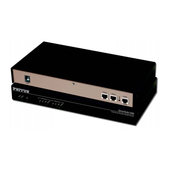
Page 18: Smartnode 5481 And 5491 Series Front Panels
SmartNode 5481 and 5491 Series Front Panels SmartNode 5481 Front Panel Figure 4 shows SmartNode 5481 Series front panel LEDs, the LED definitions are listed in table Figure 4. SmartNode 5481 Series front panel Table 4. SN5481 Front panel LEDs... -
Page 19: Smartnode 5491 Front Panel
Flashes when data is received or transmitted at the corresponding Ethernet port. SmartNode 5491 Front Panel Figure 5 shows SmartNode 5481 Series front panel LEDs, the LED definitions are listed in table 5 on page 20. Figure 5. SmartNode 5491 Series front panel... -
Page 20: Sn5491 Front Panel Leds
SmartNode 5481 & 5491 User Manual 1 • General Information Table 5. SN5491 Front panel LEDs Description Note If an error occurs, all LEDs will flash once per second. Power When lit, indicates power is applied. When lit, the unit is in normal operation. Flashes once per second during boot (startup). -
Page 21: Applications Overview
Applications Overview Chapter 2 Chapter contents Introduction ................................22 Typical Application ...............................22... -
Page 22: Introduction
2 • Applications Overview Introduction Patton’s SmartNode VoIP eSBC +Routers deliver the features you need for advanced multiservice voice and data network applications. They combine high quality voice-over-IP with powerful quality of service routing functions to build professional and reliable VoIP and data networks. This chapter describes typical applications for which this SmartNode is uniquely suited. -
Page 23: Sn5491 Typical Application
SmartNode 5481 & 5491 User Manual 2 • Applications Overview Figure 7. SN5491 typical application Typical Application... -
Page 24: Smartnode Installation
SmartNode Installation Chapter 3 Chapter contents Planning the Installation............................25 Site Log ................................25 Network Information ............................25 Network Diagram ............................25 IP Related Information ...........................25 Software Tools ..............................26 AC Power Mains .............................26 Location and Mounting Requirements ......................26 Installing the SmartNode............................26 Placing the SmartNode ...........................26 Installing Cables ..............................26... -
Page 25: Planning The Installation
26 to install the device. Site Log Patton recommends that you maintain a site log to record all actions relevant to the system, if you do not already keep such a log. Site log entries should include information such as listed in Table Table 6. -
Page 26: Software Tools
If you suspect that your AC power is not reliable, for example if room lights flicker often or there is machinery with large motors nearby, have a qualified professional test the power. Patton recommends that you include an uninterruptible power supply (UPS) in the installation to ensure that VoIP service is not impaired if the power fails. -
Page 27: Connecting The 10/100/1000Base-T Ethernet Lan And Wan Cables
Connecting the SmartNode’s DSL or Fiber port (SN5491 only) The SmartNode Model 5491 comes with an option for a SFP for Fiber WAN module. For details about the tested and compatible SFP modules please refer to http://www.patton.com/products/sfpmodules.asp. Installing the SmartNode... -
Page 28: Connecting The Power Supply
2. Verify that the AC power cord included with your SmartNode is compatible with local standards. If it is not, refer to “Contacting Patton for Assistance” on page 35 to find out how to replace it with a compatible power cord. -
Page 29: Initial
Initial Configuration Chapter 4 Chapter contents Introduction ................................30 1. Connecting the SmartNode to Your Laptop PC ....................30 2. Configuring the Desired IP Address ........................31 Factory-default IP Settings ..........................31 Login ................................31 Changing the WAN IP Address ........................32 3. Connecting the SmartNode to the Network ......................32 4. -
Page 30: Introduction
SmartNode 5481 & 5491 User Manual 4 • Initial Configuration Introduction This chapter leads you through the basic steps to set up a new SmartNode and to download a configuration. Setting up a new SmartNode consists of the following main steps: If you haven’t already installed the SmartNode, refer to chapter 3, Note “SmartNode Installation”... -
Page 31: Configuring The Desired Ip Address
SmartNode 5481 & 5491 User Manual 4 • Initial Configuration SmartNode will provide the PC with an IP address. You can check the connection to the SmartNode by exe- cuting the ping command from the PC command window as follows: ping 192.168.1.1 2. -
Page 32: Changing The Wan Ip Address
SmartNode 5481 & 5491 User Manual 4 • Initial Configuration login:administrator password: <Enter> 192.168.1.1> After you have successfully logged in you are in the operator execution mode, indicated by > as command line prompt. With the commands enable and configure you enter the configuration mode. 192.168.1.1>enable 192.168.1.1#configure 192.168.1.1(cfg)#... -
Page 33: Loading The Configuration (Optional)
4. Loading the Configuration (optional) WebWizard Community provides a collection of Wizards that help to reduce the setup time of a Patton device. Simply download the appropriate Wizard to your device, execute it locally, and you are ready to do phone calls after the SmartNode has rebooted. -
Page 34: Additional Information
Press 'yes' to restart, 'no' to cancel :yes The system is going down NOW Additional Information For detailed information about configuring and operating guidance, set up procedures, and troubleshooting, refer to the SmartNode Series SmartWare Software Configuration Guide available online at www.patton.com/ manuals. Additional Information... -
Page 35: Contacting Patton For Assistance
Contacting Patton for Assistance Chapter 5 Chapter contents Introduction ................................36 Contact Information .............................36 Warranty Service and Returned Merchandise Authorizations (RMAs)..............36 Warranty coverage ............................36 Out-of-warranty service ..........................37 Returns for credit ............................37 Return for credit policy ..........................37 RMA numbers ..............................37 Shipping instructions... -
Page 36: Introduction
(RMA). Contact Information Patton Electronics offers a wide array of free technical services. If you have questions about any of our other products we recommend you begin your search for answers by using our technical knowledge base. Here, we have gathered together many of the more commonly asked questions and compiled them into a searchable database to help you quickly solve your problems. -
Page 37: Out-Of-Warranty Service
RMA#: xxxx 7622 Rickenbacker Dr. Gaithersburg, MD 20879-4773 USA Patton will ship the equipment back to you in the same manner you ship it to us. Patton will pay the return shipping costs. Warranty Service and Returned Merchandise Authorizations (RMAs) -
Page 38: A Compliance Information
Compliance Information Appendix A Chapter contents Compliance ................................39 ................................39 Safety ................................39 Radio and TV Interference (FCC Part 15) ......................39 EC Declaration of Conformity ..........................39 Authorized European Representative ........................39... -
Page 39: Compliance
SmartNode 5481 & 5491 User Manual A • Compliance Information Compliance FCC Part 15, Class A • EN55032, Class A • EN55024 • Safety UL 62368-1/CSA C22.2 N0. 62368-1 • • IEC/62368-1 AS/NZS 62368-1 • Radio and TV Interference (FCC Part 15) This equipment generates and uses radio frequency energy, and if not installed and used properly—that is, in strict accordance with the manufacturer's instructions—may cause interference to radio and television recep- tion. -
Page 40: Specifications
Specifications Appendix B Chapter contents Data Connectivity ..............................41 Voice Processing (signaling dependent) .........................41 Fax and Modem Support............................41 Voice Signaling..............................41 IP Services ................................42 Management .................................42 System ...................................42 Physical .................................43 WAN Daughter Card (if applicable)........................43... -
Page 41: Data Connectivity
SmartNode 5481 & 5491 User Manual B • Specifications Data Connectivity Two 10/100/1000Base-Tx Gigabit Ethernet ports All ports full duplex, autosensing, auto-MDX Voice Processing (signaling dependent) Up to 64 full-duplex transcoded VoIP calls using the following CODECS: G.711 A-Law/μ-Law (64 kbps) •... -
Page 42: Ip Services
DHCP client and server (IPv4 and IPv6—Dual Stack) DNS client and relay-server, DynDNS Management Patton Cloud orchestrated Web-based GUI; Trinity WEB Wizard Industry standard CLI with remote Telnet and SSH access, fully documented HTTP & HTTPS web management and firmware loading TFTP configuration &... -
Page 43: Physical
VC queuing • Auto-configuration: TR-037 & ILMI 4.0 Interworking/Interoperability • G.SHDSL Interoperability: Alcatel Lucent Anymedia Lucent Stinger • BRAS Interoperability: Cisco Redback Fiber • 100Mbps and 1000Mbps Fiber SFP (for a list of tested SFP modules, refer to: http://www.patton.com/products/sfpmodules.asp Physical... -
Page 44: Cabling
Cabling Appendix C Chapter contents Introduction ................................45 Console .................................45 Ethernet ................................46... -
Page 45: Introduction
0 /1 0 /0 o le Serial Terminal Note A Patton Model 16F-561 RJ45 to DB-9 adapter is included with each SmartNode 5400 Series device Figure 12. Connecting a serial terminal See section “Console Port” on page 48 for console port pin-outs. -
Page 46: Ethernet
SmartNode 5481 & 5491 User Manual C • Cabling Ethernet Ethernet devices (10Base-T/100Base-T/1000Base-T) are connected to the SmartNode over a cable with RJ-45 plugs. All Ethernet ports on the SN5481/5491 are Auto-MDX use any straight or crossover cable to connect to hubs, switches, PCs or other devices. - Page 47 Port Pin-outs Appendix D Chapter contents Introduction ................................48 Console Port................................48 Ethernet ................................48 G.SHDSL Port..............................49 EFM Port ................................49 Fiber Port ................................49...
-
Page 48: D Port Pin-Outs
SmartNode 5481 & 5491 User Manual D • Port Pin-outs Introduction This section provides pin-out information for the ports of the SmartNode. Console Port Configuration settings: 9600 bps, 8 bits, no parity, 1 stop bit, no flow control 8–RTS (N/C) 7–CTS (N/C) 6–TD 5–RD... -
Page 49: G.shdsl Port
Tip 2 Tip 1 Ring 1 Ring 2 No connection No connection EFM Port Table 12. RJ-45 connector Signal Pair Ring Ring Ring Ring Fiber Port Refer to Patton’s list of tested and approved SFP modules at http://www.patton.com/products/sfpmodules.asp. G.SHDSL Port... -
Page 50: E Smartnode 5481 And 5491 Series Factory Configuration
SmartNode 5481 and 5491 Series Appendix E Factory Configuration Chapter contents Introduction ................................51... -
Page 51: Introduction
SmartNode 5481 & 5491 User Manual E • SmartNode 5481 and 5491 Series Factory Configuration Introduction Factory configuration settings for the SmartNode device can be obtained with the following command through the CLI. login: admin password: <Enter> 192.168.1.1>show config:shipping-config See chapter 4, “Initial Configuration”... -
Page 52: F Reset Button Functions
Appendix F Reset Button Functions Chapter contents Introduction ................................53 Resetting the SmartNode device when it is operating and the Power LED is lit .............54 Very exceptional case—minimal config recovery ....................54... -
Page 53: Introduction
SmartNode 5481 & 5491 User Manual F • Reset Button Functions Introduction The Reset button (see figure 16) is used to do the following: Reboot the SmartNode device (see section “Resetting the SmartNode device when it is operating and the •... -
Page 54: Resetting The Smartnode Device When It Is Operating And The Power Led Is Lit
54, the SmartNode device is still not operational, the following may remedy the problem by erasing the entire contents of flash memory (no exceptions). However it is recommended that in such a case the device be sent to Patton for analysis and repair. See section “Warranty Service and Returned Merchandise Authorizations (RMAs)”... -
Page 55: Using The Reset Button To Switch To A Backup Image
SmartNode 5481 & 5491 User Manual F • Reset Button Functions Do the following: 1. While pressing and holding the Reset button, apply power to the SmartNode device. The Power LED flashes quickly for 2 seconds, during which time the Reset button must remain pressed. 2. -
Page 56: G End User License Agreement
End User License Agreement Appendix G Chapter contents End User License Agreement ..........................57 1. Definitions ..............................57 2. Title ................................57 3. Term ................................57 4. Grant of License ............................57 5. Warranty ..............................58 6. Termination ..............................58 7. Notices ...............................58 8. Other Licenses ............................58 9. -
Page 57: End User License Agreement
End User agrees to the following conditions: 1. Definitions “Effective Date” shall mean the earliest date of purchase or download of a product containing the Patton Electronics Company Program(s) or the Program(s) themselves. “Program(s)” shall mean all software, software documentation, source code, object code, or executable code. -
Page 58: Warranty
Program(s), even if Patton Electronics Company has been advised of the possi- bility of such damages. Because some states do not allow the exclusion or limitation of liability for consequen- tial or incidental damages, the above limitation may not apply to you. -
Page 59: Unenforceable Provisions
State of Maryland, USA for any dispute arising under or relating to this agreement and waives user’s right to institute legal proceedings in any other jurisdiction. Patton shall be entitled to institute legal proceedings in connection with any matter arising under this agreement in any juris- diction where User resides, does business, or has assets.
Need help?
Do you have a question about the SmartNode 5481 Series and is the answer not in the manual?
Questions and answers