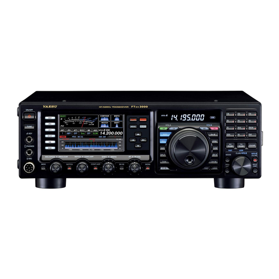
Yaesu FT DX 3000 Operating Manual
Hf/50 mhz transceiver
Hide thumbs
Also See for FT DX 3000:
- Operating manual (140 pages) ,
- Operating manual (6 pages) ,
- Operating manual (140 pages)
Advertisement
Quick Links
FCC ID: K6620461X50 / IC: 511B-20461X50
HF/50 MH
T
z
ransceiver
FT
3000
DX
O
M
peraTing
anual
YAESU MUSEN CO., LTD.
Tennozu Parkside Building
2-5-8 Higashi-Shinagawa, Shinagawa-ku, Tokyo 140-0002 Japan
YAESU USA
6125 Phyllis Drive, Cypress, CA 90630, U.S.A.
YAESU UK LTD.
Unit 12, Sun Valley Business Park, Winnall Close
Winchester, Hampshire, SO23 0LB, U.K.
YAESU HK LTD.
Unit 1306-1308, 13F., Millennium City 2, 378 Kwun Tong Road,
Kwun Tong, Kowloon, Hong Kong
Advertisement

Summary of Contents for Yaesu FT DX 3000
- Page 1 FCC ID: K6620461X50 / IC: 511B-20461X50 HF/50 MH ransceiver 3000 peraTing anual YAESU MUSEN CO., LTD. Tennozu Parkside Building 2-5-8 Higashi-Shinagawa, Shinagawa-ku, Tokyo 140-0002 Japan YAESU USA 6125 Phyllis Drive, Cypress, CA 90630, U.S.A. YAESU UK LTD. Unit 12, Sun Valley Business Park, Winnall Close Winchester, Hampshire, SO23 0LB, U.K.
- Page 2 FCC ID: K6620461X50 / IC: 511B-20461X50 . . . bout AnuAl The FT 3000 is a leading-edge transceiver with a number of new and exciting features, some of which may be unfa- miliar to you. In order to gain the most enjoyment and operating efficiency from your FT 3000, we recommend that you read this manual in its entirety, and keep it handy for reference as you explore the many capabilities of your new transceiver.
- Page 3 3000 is an elite-class HF transceiver pro- for each band. viding exceptional performance both on transmit and receive. The FT DX 3000 is designed for the most In addition, 99 memories are provided to store: Frequen- competitive operating situations, whether you primarily cy, Mode, IF filter selection, Clarifier offset, and Scan- operate in contest, DX, or digital-mode environments.
- Page 4 FCC ID: K6620461X50 / IC: 511B-20461X50 able OF OnTenTs General Description ............. 1 Interference Rejection ..........42 Accessories & Options ..........4 Receiver Operation (Front End Block Diagram) ... 42 Supplied Accessories ..........4 ATT ................. 43 Available Options ............. 5 µ-Tune Filter ............44 Before You Begin ............
- Page 5 FCC ID: K6620461X50 / IC: 511B-20461X50 able OF OnTenTs CW Mode Operation ..........72 Operation on Alaska Emergency Frequency: Setup for Straight Key 5167.5 kHz (U.S. Version Only) ........ 94 VFO and Memory Scanning ........95 (and Straight Key emulation) Operation ....72 Using the Built-in Electronic Keyer ....... 73 VFO Scanning ............
- Page 6 & O FCC ID: K6620461X50 / IC: 511B-20461X50 ccessOries pTiOns upplied cceSSorieS Hand Microphone ( MH-31 1 pc A07890001 FH-2 Remote Control Keypad DC Power Cord 1 pc T9025225 Spare Fuse (25A) 1 pc Q0000074 Operating Manual 1 pc Warranty Card 1 pc Page 4 30 00 O peraTing anual...
- Page 7 & O FCC ID: K6620461X50 / IC: 511B-20461X50 ccessOries pTiOns vAilAble ptionS MD-200 Ultra-High-Fidelity Desktop Microphone MD-100 Desktop Microphone YH-77STA Lightweight Stereo Headphone Linear Amplifier/AC Power Supply VL-1000/VP-1000 RF µTuning Kit A For 160 m Band RF µTuning Kit B For 80/40 m Bands For 30/20 m Bands RF µTuning Kit C FC-40 External Automatic Antenna Tuner...
- Page 8 FCC ID: K6620461X50 / IC: 511B-20461X50 eFOre egin xtending the ront To elevate the front panel for easy viewing, the front left and right feet of the bottom case may be extended. Pull the front legs outward from the bottom panel. Rotate the legs counter-clockwise to lock them in the extended position.
- Page 9 FCC ID: K6620461X50 / IC: 511B-20461X50 eFOre egin eSetting the icroproceSSor eSetting eMorieS Use this procedure to reset (clear) the previously stored Memory channels, without affecting any configuration changes you may have made to the Menu settings. 1. Press the front panel’s [ POWER ] switch to turn the transceiver off.
- Page 10 Able Use high-quality 50-Ohm coaxial cable for the lead-in to your FT DX 3000 transceiver. All efforts at providing an ef- ficient antenna system will be wasted if poor quality, lossy coaxial cable is used. This transceiver utilizes standard “M”...
- Page 11 FCC ID: K6620461X50 / IC: 511B-20461X50 nsTallaTiOn anD nTercOnnecTiOns rounding The FT 3000 transceiver, like any other HF communications apparatus, requires an effective ground system for maximum electrical safety and best communications effectiveness. A good ground system can contribute to station ef- ficiency in a number of ways: ...
- Page 12 FCC ID: K6620461X50 / IC: 511B-20461X50 nsTallaTiOn anD nTercOnnecTiOns onnection oF ntennA And ower AbleS Please follow the outline in the illustration regarding the proper connection of antenna coaxial cables, as well as the DC power cable. The DC power connector for the FT 3000 must only be connected to a DC source providing 13.8 Volts DC (±10 %), and capable of at least 23 Amperes of current.
- Page 13 FCC ID: K6620461X50 / IC: 511B-20461X50 nsTallaTiOn anD nTercOnnecTiOns onnection oF icrophone And eAdphone 30 00 O Page 11 peraTing anual...
- Page 14 FCC ID: K6620461X50 / IC: 511B-20461X50 nsTallaTiOn anD nTercOnnecTiOns eyer oMputer riven eying nterconnectionS The FT 3000 includes many features for the CW operator. These functions will be detailed in the “Operation” sec- tion later. Besides the built-in Electronic Keyer, two key jacks are provided, one on the front and one on the rear panel, for convenient connection to keying devices.
- Page 15 FCC ID: K6620461X50 / IC: 511B-20461X50 nsTallaTiOn anD nTercOnnecTiOns vl-1000 l ineAr MpliFier nterconnectionS Be sure that both the FT 3000 and VL-1000 are turned off, then follow the installation recommendations contained in the illustration. Please refer to the VL-1000 Operating Manual for details regarding amplifier operation. ...


Need help?
Do you have a question about the FT DX 3000 and is the answer not in the manual?
Questions and answers