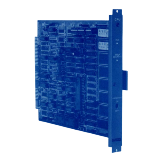
Toa CPU-52A Installation Handbook
Toa cpu-52a central processing unit: install guide
Hide thumbs
Also See for CPU-52A:
- Initial setup manual (9 pages) ,
- Functions and operating instructions (10 pages)
Summary of Contents for Toa CPU-52A
- Page 1 EXES-5000 CPU-52A INTERCOM SYSTEM TOA EXES-5000 INTERCOM SYSTEM Central Processing Unit CPU-52A INSTALLATION HAND BOOK TOA ELECTRIC CO., LTD. KOBE, JAPAN 133-21-008-4...
-
Page 2: Table Of Contents
5-2 Check of CMOS-RAM (Programmed Data Memory) 5-3 Dial Receiving Test 5-4 The Order of Link Usage DIP Switch for Function Selection on CPU-52A Station No. 200 Programming for Each Function Programming List for Functions Function Table of Stations ( 1 ) -
Page 3: Introduction
"4. Initial CPU-52A Set Up" Page 5. When you may use only some of the additional functions or equipments, it is not necessary to read instructions on unrequired functions. -
Page 4: Functions Which Require Additional Units
FUNCTIONS WHICH REQUIRE ADDITIONAL UNITS Functions of the CPU-52A which require either the addition of specific units or processing in existing units are as mentioned below. Before installation and adjustment of equipment, make sure to check your system, Additional Equip-... -
Page 5: Precautions For Installation Of Cpu-52A
3. PRECAUTIONS FOR INSTALLATION OF CPU-52A Please read following instructions carefully to ensure proper operation of the CPU-52A. 1. Be careful about damage by static electricity as the CPU-52A incorporates CMOS IC's. Do not touch com- ponents and connectors. 2. Turn off the AC power switch when you take out or insert the CPU-52A unit, or any other unit. -
Page 6: Initial Cpu-52A Set Up
Set mini-jumper (JP1) for battery from OFF to ON position. Set function selection switches (SW-A ~ SW-C) for required functions. Insert the CPU-52A into the exchange. Put all 4 link select switches of the HCU unit upward. (Link No. 15) Switch on the exchange. -
Page 7: Checking And Testing
5. CHECKING AND TESTING Check of ROM & NMOS-RAM — No calls on the system. Put the 4 "LINK SELECT" switches of the HCU upward (Link No. 15 SELECT) and switch on the AC power of the exchange. If there is no error, the indication lamps will not light. In the event of a memory error, the lamps may light as shown in the example of Fig. -
Page 8: Dial Receiving Test
5-3 Dial receiving test If you place all "LINK SELECT" switches (1 ~ 4) of SW-A on the CPU-52A in "OFF" position, conversation is impossible but the dial code from each station is indicated on the LED's of the PIU as dialed. Use this to find the cause of any fault of receiving dial information. - Page 9 6. CPU-52A DIP SWITCHS FOR FUNCTION SELECTION Link Selection ; Link No. 0 ~ 3 Link Selection ; Link No. 4 ~ 7 SW-A Link Selection ; Link No. 8 ~ 11 Link Selection ; Link No. 12 ~ 15...
-
Page 10: Station No. 200 Programming For Each Function
STATION No. 200 PROGRAMMING FOR EACH FUNCTION 1. Secretary Transfer New registration ? Station number of executive Station number of secretary Ascertain dial tone New registration finished ? Release ? Station number of executive Station number of executive A s c e r t a i n dial tone Release finished ? Is secretary's station number changed while that of executive remains unchanged ? - Page 11 2. Master/Sub-station New Registration Sub-station number Master-station number Ascertain signal tone New registration finished Release ? Sub-station number Sub-station number A s c e r t a i n signal tone A s c e r t a i n dial tone Release finished ? Is Master-station number changed while Sub-station number remains unchanged ?
- Page 12 Executive Priority New registration ? Number of station where Executive Priority is registered Ascertain signal tone Ascertain dial tone New registration finished Release Number of station where registration of Executive Priority is released Ascertain signal tone Ascertain dial tone Release finished ? Change ? Number of station where registration is released...
-
Page 13: Programming List For Functions
8. PROGRAMMING LIST FOR FUNCTIONS Use these tables to keep a record of those functions assigned to each station. Function Table For Stations (1) Function Name — 12 —... -
Page 14: Function Table Of Stations
Function Table For Stations (2) Function Name — 13 —... - Page 15 Function Table For Stations (3) Function Name — 14 —...
-
Page 16: Function Table Of Stations
Function Table For Stations (4) Function Name — 15 —... - Page 17 TOA ELECTRIC Co., Ltd. KOBE, JAPAN Printed in Japan...


Need help?
Do you have a question about the CPU-52A and is the answer not in the manual?
Questions and answers