
Related Manuals for Caple CAFF19BK


Summary of Contents for Caple CAFF19BK
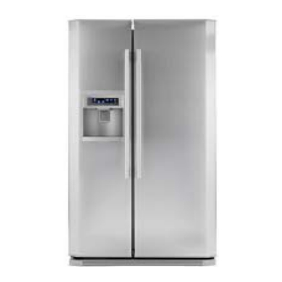
- Page 1 CAFF19BK Caple Side by Side Fridge Freezer Technical information Technical information...
- Page 8 CAFF19BK - Caple Side by Side Fridge Freezer Item Part Code Description 0060820104C freezer foamed door 0060617121 handle fix part 0060214613 bracket of touch switch 0064000270 filler lip switch 0060600070 spring of filler bracket 0060103988 Press Pad Filler Bracket 0064082811...
- Page 9 CAFF19BK - Caple Side by Side Fridge Freezer Item Part Code Description 0060820385 fridge door seal assembly,black,for CAFF19BK 0060818999 fridge top bottle seat assembly 0060207543 Egg Rack 0060818348 fridge center bottle seat assembly 0060818349 fridge bottom bottle seat assembly 0060818314...
- Page 10 CAFF19BK - Caple Side by Side Fridge Freezer Item Part Code Description 00609380509 Foot Adjustable 00608020034 Center girder screw 0060600251 Screw 0060818729 defrost waterspout assembly 0060215938B down decorating strip assembly 0060801032 Screw 00609380551 Top Drawer Left Slide Way Assembly 0060600097...
- Page 11 CAFF19BK - Caple Side by Side Fridge Freezer Item Part Code Description 0060702951 Condenser assembly 0060214381 Water Tray 00601480004 pivot 0060801032 Screw 0060213173 roller 0060702848 connection tube for suction 0060210199A Grommet Compressor Mounting 0060145577 Bushing Copper 0060803303 Bolt Compressor 0060732592...
- Page 12 CAFF19BK - Caple Side by Side Fridge Freezer Item Part Code Description 0060204650 ice box 0060600097 Screw 0060219237 Arm Bail 0064001224 Icemaker Assy 0060600097 Screw 0060205021 Nut Fixing Ice Box 0060214376 ice-maker supporter 0060214377 ice store box 0060300270 ICE BOX SEAL RING...
- Page 13 CAUTION READ THIS MANUAL CAREFULLY TO DIAGNOSE TROUBLE CORRECTLY BEFORE OFFERING SERVICE. Refrigerator SERVICE MANUAL MODEL : CAFF19SI Features: 1. Spacecraft insulation technology 2. Digital temperature with VEDA display 3. full-out fridge tray 4. Ica and water dispenser 5. Super freezing 6.
- Page 14 1. This manual is NOT intended as a comprehensive repair/maintenance guide to the appliances. 2. it should ONLY be used by suitably qualified persons having the technical competence, applicable product knowledge and suitable tools and test equipment 3. Servicing of electrical appliances must be undertaken with the appliance disconnected (unplugged) from the electrical supply 4.
-
Page 15: Table Of Contents
CAFF19SI REFRIGERATOR CONTENTS INTRODUCTION SPECIFICATION DOOR ADJUSTMENT CONTROL PANEL FUNCTIONS TEST PROCEDURES SELF DIAGNOSIS WIRING DIAGRAM PCB DIAGRAM PARTS LIST/DIAGRAM USER GUIDE PRODUCT TECHNICAL SUPPORT CONTACTS 3 of 48... -
Page 16: Introduction
CAFF19SI FRIDGE FREEZER Introduction The Caple CAFF19SI is an American side by side refrigerator. The system uses a cold blown air system. The system has only one evaporator situated in the freezer. A fan distributes the cold air around the freezer. In the top of the freezer is a damper that opens into the fridge cabinet. - Page 17 5 of 48...
-
Page 18: Specification
MODEL CAFF19SI PART 1. Specifications CAFF19SI Model 220~240/50 Cavity Supply (V/Hz) Power Consumption (Kw.h/year) Unit Dimensions 770 * 890 * 1768 WDH (mm X mm X mm) Unit Weight (Kg) Box Dimensions 960 * 770* 1894 WDH (mm X mm X mm) Box Weight (Kg) Container Quantity (40' Hc) Specifications are subject to change without prior notification. - Page 19 PART 2. Refrigeration Principle 2.1 Schematic Diagram of Refrigerating Principle Compressor Condenser Dry Filter Capillary Tube Evaporator Air Fan 2.2 Brief Description of Refrigerating Principle For the forced air cooling single-system refrigerator, there is only a finned evaporator mounted generally at the rear of its freezer compartment.
- Page 20 Positioning Your Appliance Choosing the right location This appliance should be installed in a room, This appliance which is dry and well ventilated. must be earthed In order to ensure adequate ventilation, the appliance should be at least 1,5cm clear on all sides from cabinetry, and any units placed above the appliance must be clear by 1.5cm - allowing adequate ventilation for the appliance.
-
Page 21: Door Adjustment
Positioning Your Appliance Adjustable feet Make sure that the appliance is on solid level flooring. If the refrigerator is placed on a plinth, flat, strong and fire resistant materials must be used. This appliance has front adjustable feet, which can be used to level the appliance, or adjust door alignment (see below). -
Page 22: Control Panel Functions
DISPLAY PANEL Once the fridge freezer has reached the preset temperatures the compressor will switch off. 30 minutes later the display panel will darken, This is an energy saving measure and is completely normal. This may cause the customer to contact the customer care service line to report the fridge freezer has, or keeps switching off. - Page 23 Procedure to turn off Ice Maker Press and hold Fast Freeze and Fridge Temperature Buttons for 5 seconds. This will turn off the ice maker and the lights for the Crushed Ice and Cubed Ice icons will go out. (This information is very important as it is not in the instruction manual) Procedure to turn off Fridge Press and hold Fridge Temperature button to turn off fridge 11 of 48...
-
Page 24: Test Procedures
TEST PROCEDURE REMOVE THE FRIDGE/FREEZER TOP PANEL, THEN OPEN THE PCB COVER ON THE PCB THERE IS A TEST BUTTON (SEE DIAGRAM) PRESS ONCE FOR FORCED FAN TEST . THE COMPRESSOR/FANS WILL OPERATE AND THEY SHOULD BE HEARD RUNNING. PRESS TWICE FOR FORCED DEFROST TEST. PRESS AND HOLD THE BUTTON UNTIL YOU HEAR A CONTINUOUS BEEP. - Page 25 ICE MAKER REMOVAL REMOVE THE TWO SCREWS (AS SHOWN IN THE DIAGRAM BELOW). PULL THE ICE MAKER FORWARD AND REMOVE THE PLUG CONNECTION IN THE FREEZER ROOF. THE ICE MAKER CAN THEN BE REMOVED. Screws ICE MAKER TEST PROCEDURE REMOVE THE FRIDGE/FREEZER TOP PANEL AND OPEN THE PCB COVER. ON THE PCB THERE IS A TEST BUTTON - PRESS AND HOLD THE BUTTON FOR 5/8 SECONDS, THE ICE MAKER WILL THEN OPERATE A FULL CYCLE AND REFILL WITH WATER.
- Page 26 FRIDGE AIR DAMPER OPERATION TEST The air damper is mounted at the top/back of the fridge compartment. To check the damper is working - check that there is air flowing from the vents in the front of the damper. If the fridge compartment is switched off via the control panel the damper should close and the airflow cease.
- Page 27 3.3 Control 3.3.1 Temperature Control (1) Temperature control of freezer compartment/refrigerator compartment Compressor ON or air Compressor OFF or air Item Sensor damper ON damper OFF Freezer Compartment F SNR NOTCH +1.5 NOTCH -1.5 Refrigerator R1 SNR NOTCH +1.5 NOTCH -1.5 Compartment ( 2 ) Name and position of each sensor Name...
- Page 28 ( 2 ) The compressor will be shutdown during operation if one of the following appears: During the ice-making, if ice is detected to be full, water supply is stopped. *Water inlet control ( 1 ) Check whether the ice-making tray is levelled after ice-releasing control (in normal TEST state) finishes;...
- Page 29 3.13 Fault diagnostics 3.13.1 Description and display Indication Item Description Remark F SET R SET Normal setting indication of Keys are in Normal None preset temperature Normal F SNR short Check the F (LD) SNR is Freezer setting circuit or broken connection of Normal defective...
- Page 30 INSIDE THE FRIDGE CABINET IS FREEZING Check the operation of the fridge damper. See the DAMPER TEST in the manual. If the damper fails to operate check the power supply. If the power supply is present change the damper assembly. If there is no power supply change the PCB.
- Page 31 19 of 48...
- Page 32 20 of 48...
- Page 33 Item Description Cable's colour Power supply strain PCB 64000595 Frequency conversion PCB 64000594 Compressor Display PCB 64000253 Main PCB 64000823 In power L Brown In power N Blue Out power L Brown Out power N Blue Frequency conversion PCB input (negative) Black Frequency conversion PCB output (positive) Frequency conversion PCB output...
- Page 34 Item Description Cable's colour Display PCB voltage output Red/White Display PCB voltage input Yellow Display PCB signal output Orange Display PCB signal feedback Environment sensor Double White Freezer sensor Double White Defrost sensor Double Orange Freezer door switch signal Double Red Fridge sensor Double Grey Fridge sensor...
- Page 35 23 of 48...
- Page 36 24 of 48...
- Page 37 25 of 48...
- Page 38 26 of 48...
- Page 39 27 of 48...
- Page 40 REFRIGERATOR CAFF19SI GENERAL ASSEMBLY No. in the Failure Spare parts number Description exploded Rate 0060821734 fridge foamed door assembly 0.05% 0060821735 freezer foaming door assembly 0.00% 0060821346 lower vegetable box assembly 0.00% 0060219817 right slide way of lower vegetable box 0.00% 0060600097 screw...
- Page 41 REFRIGERATOR CAFF19SI No. in the Failure Spare parts number Description exploded Rate 0060215015 seal strip 11 0.00% 0060801032 screw 0.00% 0060818345 compressor bracket assembly 0.00% 0060703449 connection tube for exhaust 0.00% 0060806084 valve 0.00% 0060400035 cable of valve 0.00% 0060210199A rubber grommet 0.00% 0060803303...
- Page 42 REFRIGERATOR CAFF19SI No. in the Failure Spare parts number Description exploded Rate 0060214630 refrigerator top lampshade 0.00% 0060215432 dryer fix slip 0.01% 0060207543 egg rack 0.00% 00606050061 lamp switch 0.00% 0060214565 fridge shelf 0.00% 0060821344 foamed cabinet assembly 0.12% 0060214565 fridge shelf 0.00% 0060818319...
- Page 43 REFRIGERATOR CAFF19SI No. in the Failure Spare parts number Description exploded Rate 0060205622 filler cover 0.00% 0060214992 switch plywood 0.00% 0060600096 jiggling switch 0.00% 0064082811 cross groove self attach screw 0.00% 0060214609 bracket of control board 0.00% 0060301125 protection cover tray of filler 0.00% 0060818937B dispenser outsider bucket...
- Page 44 REFRIGERATOR CAFF19SI ICE-CRUSHED BOX ASSEMBLY No. in the Failure Spare parts number Description exploded Rate 0060214377 ice store box 0.00% 0060300270 ice box seal ring 0.00% 0060205623 shaft cover of push shaft 0.06% 0060161361 ice push screw 0.00% 0060600067 wrest spring of dial pole 0.00% 0060103727 bracket of dial pole...
- Page 49 220-240 220-240...
- Page 54 Fixing of bottom decorate Fixing of bottom decorate...
- Page 63 Technical Support Contacts CAPLE CAFF19SI Caple customer service Telephone 0117 938 1900 0117 938 7441 E-mail service@caple.co.uk THANK YOU FOR CHOOSING CAPLE 48 of 48...
- Page 64 CAFF19** TRAINING...
- Page 65 Contents 1. Characteristic 2. Configuration 3. Principle of system 4. About sensors 5. About functions 6. Circuit diagram 7. Inspection of familiar fault 8. Familiar fault inspection of control panel 9. Comparison of temperature and sensor resistance...
-
Page 66: Characteristic
1. Characteristic 1)This is a series of computer- controlled, one-system refrigerator, with one evaporator in freezing room and the temperature of refrigerating room is adjusted by the on-off of the refrigerating electro-vent. 2)Bar in the refrigerating door, get things without opening the door every time. -
Page 67: Configuration
2. Configuration... -
Page 68: Principle Of System
3. Principle of system 1、 Total wind cooling, evaporator in freezing room, cooling of refrigerating room is achieved through a fan in the freezing room. 2、Main parts in the refrigerating room: Refrigerating fan, refrigerating bulb, refrigerating sensor R1/R2, Drawer and glass shelves. 3、Main parts in the freezing room: Freezing fan (direct currency), ice-dispenser assembly, cover of evaporator, freezing evaporator, defrost... -
Page 69: About Sensors
4. About sensors (RT) 1. Location of (R1) sensors: (ICE) Disp. (R2) - Page 70 About sensors 2、 Sensors fault code: RT SNR is defective Refrigerator setting 1 glitters R1 SNR is defective Refrigerator setting 2 glitters R2 SNR is defective Refrigerator setting 3 glitters F (LD)SNR is defective Freezer setting 1glitters CAFF19 D(HS) SNR is defective Freezer setting 2 glitters ICE SNR is defective Freezer setting 3 glitters...
- Page 71 About sensors 3. Control of sensor fault: Load control Items Vent of freezing compressor Defrost heater vent department Normal Normal Normal Normal Normal 15minON/ F SNR Fault Medium speed Normal Normal 15minOFF Normal 10min on/ R1 SNR Fault 1300RPM Normal 15min off Normal Normal...
-
Page 72: About Functions
About functions operation: 1: ① 30 min after last operation the display will be switched off, press any button or open any door, the display will resume. ② By first electrify, if the temperature of refrigerator room is between on and off temperature, the appliance will remain shut down. - Page 73 Functions 2、Control of air-escaper: ① Control of freezing air escaper: open the refrigerating door, the refrigerating air escaper will be turned on, and the freezing fan will be working, after 2 minutes the refrigerating air escaper will be turned off. If the freezing fan works at a speed of 1500 RPM, when the freezing door is open, the freezing fan will keep working but switch to 1300 RPM.
- Page 74 Functions 3、defrost: • Automatic defrost: after added up to 7 hours of compressor running, defrost will be switched on. When defrost SNR reaches 7℃, defrost will be over. • After 120 minutes of defrost, and the defrost SNR still have not reached 7℃, the defrost heater will be cut off and alarm on: 4th bar of refrigerating glitters.
- Page 75 Functions 5、 Ice-making system: ① Dispenser: can get water or ice only with the freezing door shut, choose between cool water/ cube/ crushed ice, press button and the electromagnet valve will be working and will open the ice cover. Let go of the button, ice cover will be closed in 5 seconds.
- Page 76 functions ⑤ Before ice-maker closed After ice-maker closed How to turn off the ice-maker: • press the refrigerating and super freezing buttons at the same time for 3 seconds, after a beep, the cube and crushed ice symbol will be off, the ice maker stops working ⑥...
- Page 77 functions ⑧ Adjust the water timing • In case of leakage, stick together of ice cubes or over-size ice cubes, the water volume is more than necessary. Change the timing. • Adjust the button on the main control board, follows is a comparison of timing and parameter.
- Page 78 Functions 6、Scenograph of water supply system: water runs through water drain pipe, and be divided into two ways: one way goes to water bottle of freezing room and then comes out through water dispenser. The other goes through pipe at the back of refrigerator and into ice-maker.
- Page 79 Functions 7、About testing function: ① With self-testing function, the appliance can quickly check the working condition of fan, compressor and defrost heater. ② How to enter and quit: press the test button on the main control board once, and enter the forced starting mode, and a second time to enter forced defrosting mode.
-
Page 80: Circuit Diagram
6. Circuit diagram... - Page 81 7. Inspection of familiar fault—ice-maker • Fault 1:no ice-making; • Steps of test: • 1)test the temperature of freezing room reaches the set temperature. • 2)see if the ice-maker is shut down • 3)press the test button on the main control board for 3 seconds, enter the testing mode to see if the ice-maker can turn over.
- Page 82 Inspection of familiar fault—ice-maker • Fault 2:third bar of freezing glitters • steps: • 1) third bar of freezing glitters means the fault of sensor of ice-maker. Check the joint of ice-maker, make sure there is no water, rust or corrupt. If there is any, clean the joint and reconnect.
-
Page 83: Inspection Of Familiar Fault
Inspection of familiar fault—ice-maker • Fault 3:no crushed ice • steps: • 1)open the freezing door, make sure the selecting bar under the storage box is good shape or not stick into the selecting valve. • 2)disassemble the ice storage box, make sure the ice blade is in fine shape. - Page 84 Inspection of familiar fault—ice-maker • Fault 4:no ice cube; • steps: • 1)open the freezing door, make sure the selecting bar under the storage box is good shape or not stick into the selecting valve. • 2)disassemble the ice storage box, check if the ice cubes are stick together.
- Page 85 Inspection of familiar fault—ice-maker • Fault 5:noise of ice-maker; • steps: • Enter the test mode of ice-maker, see if the ice-maker touches the water pipe when turns over. If so, disassemble the ice-maker, move it forward a little and re-fix it. •...
- Page 86 Familiar fault testing method-electro-air escaper • Fault 1:refrigerating temperature is too low, food frozen. • Steps: • Press the refrigerating adjust button for more than 3 seconds, until the light turns off, which means refrigerating room is shut down. • Open the refrigerating door, see if there is cool water near the air-escaper.
- Page 87 Testing method of control panel—main board • Fault1:no display, no start-up; • steps: • Check the power cable is normal; • Disassemble the display board and freezing door upper hinge, check the display board is connected correctly. • Open the control board cover and check if there is any voltage input on main board, if no, check the rejector board fuse is normal.
- Page 88 Testing method of control panel—main board • Fault 2:failure of freezing air escaper • steps: • Open the freezing door, press the freezing bulb button, to see if the fan works. • Open the main board cover, press the test button, enter forced start-up mode to see if the fan works, if not, check the CN2 control panel and freezing fan joint is normal or not.
- Page 89 8. Testing method of control panel...
-
Page 90: Comparison Of Temperature And Sensor Resistance
9. Comparison of temperature and sensor resistance... - Page 91 Comparison of temperature and sensor resistance...
- Page 92 The End. Please point out the mistakes in this book, we hope you can learn more about this model of refrigerator, and therefore your repairing skills will be better.
- Page 93 Water Pipeline Connection Instruction Operating Instruction of Water Pipeline Connection The inlet pipeline components, which are accessories, include: water filter, connecting nuts, pipe fixing nuts, guide post, 15m PE water pipe, 4/3~1/4 adapter, etc. The packaged assembly is shown as follows and is kept in the vegetable box of a refrigerating chamber.
- Page 94 Water Pipeline Connection Instruction Installation Procedure: 1. Take out the water filter. 2. Dismount and discard the covers on both ends of the water filter. Page 2 of 9...
- Page 95 Water Pipeline Connection Instruction 3. Fix the wider side of connecting nut to the water filter; this procedure applies to both sides. 4. Insert the narrower side of guide post to Φ6mm water pipe and let the cap project outside; then insert the pipe fixing nut into water pipe, as shown in following picture.
- Page 96 Water Pipeline Connection Instruction 5. Fix the pipe fixing nut to connecting nut, according to following picture, and fasten them. 6. Fix both sides of the water filter. Page 4 of 9...
- Page 97 Water Pipeline Connection Instruction 7. Unscrew fixing nuts of the water valve at the back of refrigerator. 8. Insert ф6mm PE pipe into the fixing nut. Page 5 of 9...
- Page 98 Water Pipeline Connection Instruction 9. Fix the Φ6mm water pipe onto the water valve. 10. Insert Φ6mm water pipe into pipe fixing nut and then revolve the pipe to fix it with the pipe joint. Page 6 of 9...
- Page 99 Water Pipeline Connection Instruction 11. The effect of fixed pipe components is shown as follows. Page 7 of 9...
- Page 100 Water Pipeline Connection Instruction 12. Position the fixing clamp according to following picture to the wall or a desired place, and then fix it with screw. 13. Fix the water filter onto the fixing clamp and fasten the filter. Page 8 of 9...
- Page 101 Water Pipeline Connection Instruction 14. Fix the 3/4’ internal thread end of pipe joint to the outlet end of water supply; the outlet of supply is required to have 3/4’ external thread. For the connection with accessory pipe joint, the user may choose household 3/4’ external thread tap, 3/4’...
Need help?
Do you have a question about the CAFF19BK and is the answer not in the manual?
Questions and answers