Advertisement
Quick Links
Advertisement

Related Manuals for Microaces D8084


Summary of Contents for Microaces D8084
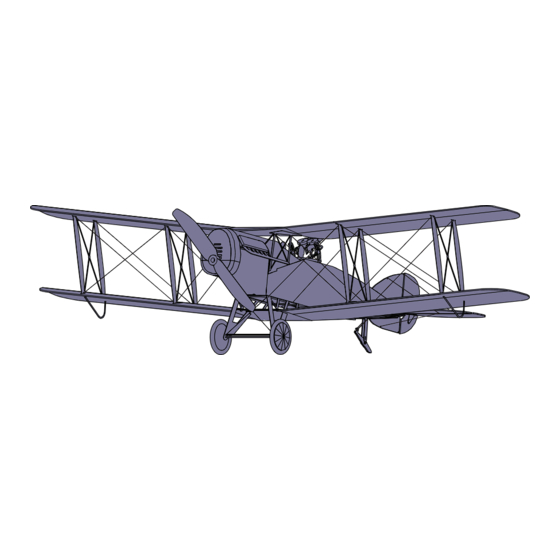
- Page 1 ASSEMBLY GUIDE Bristol F.2b...
-
Page 2: Warranty
It is extremely important to us that you and those around you remain safe while building and flying Microaces kits. Please take note of the following notices of safety. Microaces Aero kits contain parts and packaging unsuitable for handling by small children. Please ensure that children under the age of 6 years are prevented from handling the component parts or packaging of this kit. -
Page 3: Kit Parts
KIT PARTS Sheet Parts 1 x 2mm Laser cut Depron airframe 1 x 1mm printed & laser cut Depron fuselage 2 x 1mm printed & laser cut Depron flight surfaces 2 x 200 micron printed & laser cut polypropylene 1 x polyester sticker sheet Loose Parts 1 x 0.8mm laser cut plywood motor mount 2 x neoprene tyres... - Page 4 2mm FOAM 1mm DEPRON FOAM...
- Page 5 1mm DEPRON FOAM Z20a Z21a...
- Page 6 1mm DEPRON FOAM STICKERS...
-
Page 7: Plastic Parts
PLASTIC PARTS P51(s) P53(p) P54(p) P52(s) (+2 washers) - Page 8 SCORING & BEVELING GUIDE #1 Method for scoring 1mm Depron Using a straight edge as a guide, score the depron with the reverse side of a craft knife or a ball point pen. If you haven’t used this technique before it is essential that you practice using a scrap or spare piece of 1mm Depron prior to processing any kit components.
- Page 9 SCORING & BEVELING GUIDE #2 Method for scoring 1mm Depron Using a straight edge as a guide, score the depron with the reverse side of a craft knife or a ball point pen. If you haven’t used this technique before it is essential that you practice using a scrap or spare piece of 1mm Depron prior to processing any kit components.
- Page 10 STAGE 1 AIRFRAME The plastic parts used in the airframe are there to increase the strength of the structure in vital areas whilst still providing some flexibility. Apply a thin layer of adhesive to the plastic part and attach immediately to allow some wiggle time to get the parts lined up.
- Page 11 Note: D4 former assembly STAGE 1 AIRFRAME Note D6 has a slight backward slant compared to the rest of the upright formers.
- Page 12 Bevel & Score before installation - STAGE 2 FUSELAGE See Scoring & Bevelling guide #1 Dry fitting before gluing Attach the fuselage skin in stages, checking at each stage that alignment is good. Don’t forget, you can always dissolve UHU por with naphtha (lighter fluid) applied to joins with a small hobbyists paint brush if you want to start over! Note position of forward...
- Page 13 STAGE 2 FUSELAGE Bevel & Score before installation - See Scoring & Bevelling guide #2 P7 x4 Carbon Fibre 33mm x 1.0mm x 0.4mm 2 off 20.5mm Dry fitting before gluing Bevel & Score before installation - See Scoring & Bevelling guide #2...
- Page 14 STAGE 3 TAIL Carbon Fibre 165mm x 1.0mm x 0.4mm 180° 180° Ensure Horizontal and Vertical surfaces are perpendicular to one another and aligned with the fuselage...
- Page 15 STAGE 4 UNDERCARRIAGE Bevel & Score before installation - See Scoring & Bevelling guide #2 70mm x 0.4mm x 1.0mm Carbon Fibre 2 off Fold 35mm x 0.4mm x 1.0mm Carbon Fibre 2 off Fold...
- Page 16 STAGE 4 UNDERCARRIAGE Bevel & Score before installation - See Scoring & Bevelling guide #2 47mm x 0.4mm x 1.0mm Carbon Fibre Lubricate sticker with soapy water to slide it into place.
- Page 17 STAGE 4 UNDERCARRIAGE Elastic Band 5mm x Ø1mm Carbon Fibre...
- Page 18 STAGE 5 CHIN 8mm x 50mm Sanding Stick Ø x 1mm Magnets x 2 Paper Strip STAGE 6 CABANE STRUTS Slot the carbon fibre supports into the holes provided in the top of the cabane struts. Measure the distance between the top of the two struts and adjust to 47-48mm. If excess carbon fibre protrudes through the struts, remove once glue is dry and prior to upper wing installation.
- Page 19 STAGE 7 EXHAUST EXTENSION P51s P52s P53p P54p 90° 45°...
- Page 20 STAGE 8 LOWER WING Wing Slot Z12a Bevel & Score before installation - See Scoring & Bevelling guide #2 Z11a...
- Page 21 * Carbon Fibre STAGE 9 INTERPLANE STRUTS 60mm x 1.0mm x 0.4mm 8off Insert wing skids into holes provided under wing...
- Page 22 STAGE 10 PRE-RIGGING...
- Page 23 STAGE 11 UPPER WING Bevel & Score before installation - See Scoring & Bevelling guide #2 * Carbon Fibre 70mm x 1.0mm x 0.4mm 2off 180˚ Carbon Fibre D17/S23...
- Page 24 STAGE 11 UPPER WING Z21a Bevel & Score before installation - See Scoring & Bevelling guide #2 Open up the two scored slots in wing fillet parts using knife Be careful NOT to cut all the way across fillets Z20a Wing Slot Z20a Z21a...
- Page 25 Mounting the Wing STAGE 11 UPPER WING A dry run without glue is recommended to familiarise yourself with the process. Step 1: Attach cabane (inner) struts to the centre section of the upper wing. Ensure the tabs on top of the cabane struts insert fully into the corresponding slots in the upper surface of the wing.
-
Page 26: Front View
STAGE 12 RIGGING TENSION FRONT VIEW Ensure correct alignment when tensioning the rigging The rigging on the Bristol is functional. It strengthens and stabilises the wings to provide predictable flight characteris- tics so is important to get right! Stabalise the wire on both sides of the aircraft at the lower points on the undercarriage with some CA or Alphatic resin adhesive. - Page 27 STAGE 13 NOSE HATCH Sanding Stick 8mm x 80mm Paper Strip Bevel & Score before installation - See Scoring & Bevelling guide #2 Magnets x 2 Ensure magnets match magnets previously installed in chin. Ensure magnet matches polarity of magnet installed in fuselage.
- Page 28 STAGE 13 NOSE HATCH Sanding Stick Sanding Stick repeat with second exhaust on other side...
- Page 29 STAGE 14 ADDITIONAL DETAIL 3mmØ Clear plastic tube S13 Assembly...
- Page 30 STAGE 14 REAR GUN & MOUNT/PILOT Pilot...
- Page 31 Bevel & Score Z15 & Z16 before installation - STAGE 15 WHEELS See Scoring & Bevelling guide #2 Assemble each wheel onto the axle temporarily to ensure good alignment. 1mmØ x 75mm Carbon Fibre DO NOT GLUE TO AXLE AT THIS STAGE Allow +2hrs for Rubber Tyre glue to cure before...
- Page 32 STAGE 17 CONTROLS Control Wire Control Wire (Rudder) (Elevator) View from Above View from Below Control Wire Control Wire (Elevator) (Rudder) Building Tip The Control Horns for the rudder and elevator are very flexible. Install the control 90˚ 90˚ wires for each and use tweezers to bend the horns to insert the ‘Z’ bend into the hole. Use the outer hole of the control horns for more gentle control of your aircraft!
- Page 33 Battery Mounting Plate STAGE 18 MOTOR & PROPELLER Complex Stickers can be applied by wetting the adhesive side to aid positioning Prop Sticker Plywood Motor Mounting Plate Prop Recommended Sticker GWS5043 propeller Motor Gearbox Propeller Prop Adapter Battery Position...
- Page 34 STAGE 19 DRAG LINES Use existing Rigging Hole in top of strut to secure Drag Line. Trim excess once rigging is secured. STAGE 20 PITOT TUBE 48mm STAGE 21 FUEL PROP P55 washers Piano Wire 7mm Long Fuel Prop...
- Page 35 STAGE 22 FINISHING TOUCHES Centre of Gravity (CoG) With all the electronics installed including the battery, the CoG should be around the apex of the top wing as shown on the diagram below. Balance on finger tips to see if the aircraft balances at this point. Before add- ing any weight it is advisable to perform a glide test.
- Page 36 STAGE 23 Optional Cooper Bomb Rack Pale Yellow 81 - Humbrol Matt 3D Printed Ordinance Green Sticker Red Sticker Matt Black Paint...
- Page 37 STAGE 24 Optional RL112lb HE Bomb Rack...
- Page 38 STAGE 24 Optional RL112lb HE Bomb Rack FOLD FOLD Pale Yellow 81 FOLD - Humbrol Matt FOLD 3D Printed Ordinance Green Sticker Red Sticker...
- Page 39 STAGE 25 EXTERNAL RADIATOR .TTROP Section of Rubber Tyre Section of Rubber Tyre Position of Radiator on fuselage...
Need help?
Do you have a question about the D8084 and is the answer not in the manual?
Questions and answers