Advertisement
Quick Links
Advertisement

Related Manuals for Microaces PERCEE


Summary of Contents for Microaces PERCEE
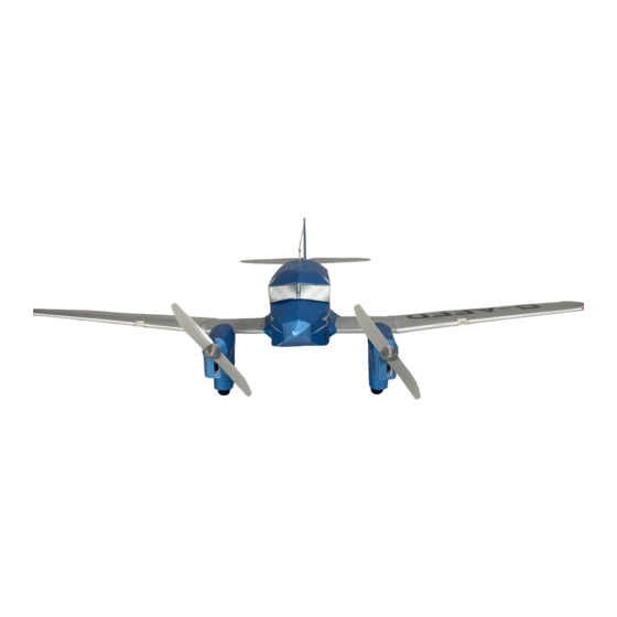
- Page 1 ASSEMBLY GUIDE PERCEE Inspired by the Percival Q6 Petrel Version 1...
- Page 2 It is extremely important to us that you and those around you remain safe while building and flying Microaces kits. Please take note of the following notices of safety. Microaces Aero kits contain parts and packaging unsuitable for handling by small children. Please ensure that children under the age of 6 years are prevented from handling the component parts or packaging of this kit.
-
Page 3: Kit Parts
Aliphatic Resin or Foam safe cyano glue (for rigging & re-inforcement) RECOMMENDED ELECTRONICS The Microaces Percee is designed around a Micro SR3X 5 channel 2.4GHz receiver, with twin ESC for brushed motor operation AND 3 Axis Stabilization. Recommended servos are 2 (for 3 channel operation) or 4 (for 4 channel operation) 1.7g low voltage micro digital servos. - Page 4 2mm FOAM...
- Page 5 2mm FOAM...
- Page 6 TYVEK PARTS IMPORTANT INFORMATION ON GLUING TYVEK Tyvek may distort when exposed to glues that use a petroleum or aliphatic solvents. When assembling Tyvek parts & panels using UHU por or similar petroleum or aliphatic based contact adhesives, allow the glue to thoroughly dry before attaching.
- Page 7 TYVEK PARTS IMPORTANT INFORMATION ON GLUING TYVEK Tyvek may distort when exposed to glues that use a petroleum or aliphatic solvents. When assembling Tyvek parts & panels using UHU por or similar petroleum or aliphatic based contact adhesives, allow the glue to thoroughly dry before attaching.
- Page 8 TYVEK PARTS IMPORTANT INFORMATION ON GLUING TYVEK Tyvek may distort when exposed to glues that use a petroleum or aliphatic solvents. When assembling Tyvek parts & panels using UHU por or similar petroleum or aliphatic based contact adhesives, allow the glue to thoroughly dry before attaching.
-
Page 9: Plastic Parts
PLASTIC PARTS... - Page 10 1mm PARTS...
- Page 11 1mm PARTS...
- Page 12 0.8mm PLYWOOD STICKERS...
- Page 13 SCORING & BEVELING GUIDE #1 Method for scoring 1mm Foam Using a straight edge as a guide, score the Foam with the reverse side of a craft knife or a ball point pen. If you haven’t used this technique before it is essential that you practice using a scrap or spare piece of 1mm Foam prior to processing any kit components.
- Page 14 SCORING & BEVELING GUIDE #2 Method for scoring 1mm Foam Using a straight edge as a guide, score the Foam with the reverse side of a craft knife or a ball point pen. If you haven’t used this technique before it is essential that you practice using a scrap or spare piece of 1mm Foam prior to processing any kit components.
- Page 15 SCORING & BEVELING GUIDE #3 Method for scoring 1mm Foam Using a straight edge as a guide, score the Foam with the reverse side of a craft knife or a ball point pen. If you haven’t used this technique before it is essential that you practice using a scrap or spare piece of 1mm Foam prior to processing any kit components.
- Page 16 Apply a thin layer of adhesive to the plastic part and attach immediately to allow some wiggle time to get the parts lined up. Set aside to cure. Use Stage 1 Engine Nacell Instructions to create both Percee engine nacelles...
- Page 17 STAGE 1 ENGINE NACELLE...
- Page 18 STAGE 1 ENGINE NACELLE Wheel 2mm dia x 18mm Carbon Fibre axle Flex undercarriage legs apart to install wheel V16a...
- Page 19 STAGE 1 ENGINE NACELLE See Important Information on gluing Tyvek before proceeding Curl the Tyvek using a dowel, paint brush handle or something similar. 90˚ See Important Information on gluing Tyvek before proceeding...
- Page 20 STAGE 1 ENGINE NACELLE See Important Information on gluing Tyvek before proceeding Score TN5b TN8b - required on second Nacelle build See Important Information on gluing Tyvek before proceeding TN5a TN8a - required on second Nacelle build See Important Information on gluing Tyvek before proceeding...
- Page 21 STAGE 1 ENGINE NACELLE 2mm foam can be readily carved with a fresh, sharp blade for quick results Ø x 1mm Magnet’s Ensure the magnets are correctly oriented before installation. Do this by matching them to the magnets installed in the chin before installing it here.
- Page 22 STAGE 1 ENGINE NACELLE pre-bend mesh area of P13 before assembling TN7 TN10 - required on second Nacelle build See Important Information on gluing Tyvek before proceeding...
- Page 23 STAGE 2 FUSELAGE...
- Page 24 STAGE 2 FUSELAGE...
- Page 25 STAGE 2 FUSELAGE...
- Page 26 STAGE 2 FUSELAGE...
- Page 27 STAGE 2 FUSELAGE Fold See Important Information on gluing Tyvek before proceeding Fold Fold Fold See Important Information on gluing Tyvek before proceeding Fold Fold Fold Fold...
- Page 28 Fold STAGE 2 FUSELAGE Fold Fold See Important Information on gluing Tyvek before proceeding Fold See Important Information on gluing Tyvek before proceeding Fold Fold Fold Fold...
- Page 29 STAGE 2 FUSELAGE Always Dry fit before gluing Add glue to the surface the highlighted area comes into contact with. Avoid adding glue directly to Tyvek if possible See Important Information on gluing Tyvek before proceeding See Important Information on gluing Tyvek before proceeding...
- Page 30 STAGE 2 FUSELAGE Attaching the Tyvek skin to the fuselage is best done in stages. As the material is very flexible it can See Important Information on gluing be held away from the frame while Tyvek before proceeding adhesive is applied and allowed to dry before assembling T11B Underside of part...
- Page 31 STAGE 2 FUSELAGE See Important Information on gluing Tyvek before proceeding Score & Bevel before installation - See Scoring & Bevelling guide #2...
- Page 32 STAGE 2 FUSELAGE See Important Information on gluing Tyvek before proceeding...
- Page 33 STAGE 3 WINGS Score & Bevel before installation - See Scoring & Bevelling guide #2 See Important Information on gluing Tyvek before proceeding...
- Page 34 STAGE 3 WINGS Before installing any electronics, ensure all cables, connectors, extension wires, servos and motors are working by plugging them in to their respective connectors on the receiver, binding the receiver to your transmitter and testing they function as expected. Install extension wires before the wing Aileron servo Y cable extension skin is attached to the underside...
- Page 35 STAGE 3 WINGS Also fit Nacelle to starboard side...
- Page 36 STAGE 3 WINGS See Important T20 on Information on gluing starboard side Tyvek before proceeding Underside of part T21 on starboard side See Important Information on gluing Tyvek before proceeding Gluing area See Important Information on gluing Tyvek before proceeding T22 on starboard side Gluing area...
- Page 37 STAGE 3 WINGS See Important Information on gluing Tyvek before proceeding TN6 & TN9 STAGE 4 TAIL Bevel before installation - See Scoring & Bevelling guide #2 Carbon Fibre 165mm x 3.0mm x 0.4mm 1 mm...
- Page 38 STAGE 4 TAIL Score & Bevel before installation - See Important Information on See Scoring & Bevelling guide #3 gluing Tyvek before proceeding Score & Bevel before installation - See Scoring & Bevelling guide #3...
- Page 39 STAGE 5 HATCH V46A See Important Information on Fold Lines gluing Tyvek before proceeding T30a T27a Ensure the magnets are correctly oriented before installation. Do this by matching them to the magnets Ø x 1mm installed in the chin Magnet x2 before installing it here.
- Page 40 STAGE 6 WINGS...
- Page 41 STAGE 6 WINGS...
- Page 42 Remove if installing aileron controls to kit STAGE 6 WINGS Score & Bevel before installation - See Scoring & Bevelling guide #1 See Important Information on gluing Tyvek before proceeding...
- Page 43 STAGE 6 WINGS See Important Information on gluing Tyvek before proceeding...
- Page 44 Ensure servos are centred before STAGE 6 WINGS installation. Do this by connecting to the bound receiver and ensuring the trim on the transmitter is neutral Servo Servo...
- Page 45 STAGE 6 WINGS Use T24 & T26 to cover join...
- Page 46 STAGE 6 WINGS Use T23 & T25 to cover join Fit servos before installing servo arms to Ensure servos are centred before make control rod attachment easier installation. Do this by connecting to the bound receiver and ensuring the trim on Elevator Servo the transmitter is neutral Rudder Servo...
- Page 47 STAGE 7 CONTROL HORNS...
- Page 48 STAGE 7 CONTROL RODS Create wireforms from the 4 supplied piano wire control rods using pliers & wire cutters Only glue in place once installed and tested...
- Page 49 Top View STAGE 7 CONTROL RODS Position of receiver for installation use double sided servo tape...
- Page 50 STAGE 8 ELECTRONICS Battery Placement...
- Page 51 STAGE 9 NOSE ASSEMBLY 2mm foam can be readily carved with a fresh, sharp blade for quick results GWS4530R GWS4530...
- Page 52 Radio Control Recommendations If the recommended electronics have been supplied by Microaces, the receiver will have been set up to operate with the Percee model. But Nose Heavy please check before flying to ensure flight surfaces are operating in the required direction and reverse any Add weight to Tail! that aren’t, on your transmitter* if required.
Need help?
Do you have a question about the PERCEE and is the answer not in the manual?
Questions and answers