Advertisement
Quick Links
Advertisement

Related Manuals for Microaces Fokker Dr.1


Summary of Contents for Microaces Fokker Dr.1
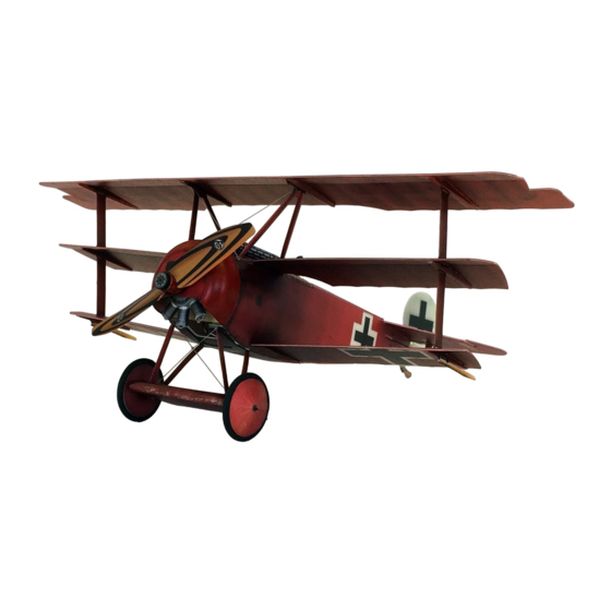
- Page 1 ASSEMBLY GUIDE Dr.I Dreidecker Version 2...
- Page 2 It is extremely important to us that you and those around you remain safe while building and flying Microaces kits. Please take note of the following notices of safety. Microaces Aero kits contain parts and packaging unsuitable for handling by small children. Please ensure that children under the age of 6 years are prevented from handling the component parts or packaging of this kit.
-
Page 3: Kit Parts
Steel Rule or straight edge Sanding Stick or sand paper (180 grit recommended) Tweezers Needle threader or Microaces Rigging Tool Needle nose pliers & wire cutters Deluxe Materials Foam 2 Foam adhesive Aliphatic Resin or Foam safe cyano glue (for rigging & re-inforcement) - Page 4 2mm FOAM...
-
Page 5: Plastic Parts
PLASTIC PARTS... - Page 6 1mm PARTS...
- Page 7 1mm PARTS...
- Page 8 0.8mm PLYWOOD STICKERS...
- Page 9 SCORING & BEVELING GUIDE #1 Method for scoring 1mm Foam Using a straight edge as a guide, score the Foam with the reverse side of a craft knife or a ball point pen. If you haven’t used this technique before it is essential that you practice using a scrap or spare piece of 1mm Foam prior to processing any kit components.
- Page 10 STAGE 1 AIRFRAME The plastic parts used in the airframe are there to increase the strength of the structure in vital areas whilst still providing some flexibility. Apply a thin layer of adhesive to the plastic part and attach immediately to allow some wiggle time to get the parts lined up.
- Page 11 STAGE 1 AIRFRAME Remove foam indicated by shading to allow for battery positioning. Parts are pre-scored as a guide...
- Page 12 STAGE 2 FUSELAGE Score & Bevel before installation - See Scoring & Bevelling guide #1 Dry fit before gluing...
- Page 13 STAGE 2 FUSELAGE Dry fit before gluing...
- Page 14 STAGE 3 TAIL Carbon Fibre 92mm x 1.0mm x 0.4mm...
- Page 15 STAGE 4 LOWER WING D14/S6 D14/S6...
- Page 16 STAGE 4 LOWER WING Time 1 Hour...
- Page 17 STAGE 4 LOWER WING Dry fit before gluing...
- Page 18 STAGE 5 CENTRAL WING D14/S6 D14/S6...
- Page 19 STAGE 6 STRUTS P8/P7/P6 Only glue in place after top wing is installed P5/P9/P10 Only glue in place after top wing is installed...
- Page 20 STAGE 6 STRUTS Carbon Fibre 41mm x 1.0mm x 0.4mm Carbon Fibre 41mm x 1.0mm x 0.4mm Carbon Fibre 41mm x 1.0mm x 0.4mm Carbon Fibre 41mm x 1.0mm x 0.4mm...
- Page 21 STAGE 7 UNDERCARRIAGE Carbon Fibre 31mm x 1.0mm x 0.4mm Carbon Fibre 31mm x 1.0mm x 0.4mm Rear Front Tighten rigging and secure at position D. Remove excess with sharp knife.
- Page 22 STAGE 7 UNDERCARRIAGE Bevel & Score before installation - See Scoring & Bevelling guide #1...
- Page 23 STAGE 7 UNDERCARRIAGE...
- Page 24 STAGE 8 TOP DECK Only secure rigging once top wing is installed Bevel & Score before installation - See Scoring & Bevelling guide #1 STAGE 9 GUNS...
- Page 25 STAGE 9 GUNS 1 x 50mm x 4mm Ø black plastic tube...
- Page 26 STAGE 10 UPPER WING D19/S8 D17/S7 D17/S7 D19/S8 Dry fit before gluing Ensure the tabs on the top of the strutwork insert fully into the corresponding slots in the wing. Secure and allow adhesive to set. Interplane Cabane Cabane Interplane...
- Page 27 STAGE 11 MOTOR MOUNT Ensure the magnet is correctly oriented before installation. Do this by matching it to the magnet installed in the fuselage firewall before installing it here. Ø 4mm x 1mm magnet...
- Page 28 STAGE 12 ROTARY ENGINE Brass Tube 2mmØ x 12mm Straw 4mmØ Motor Gearbox (Long Shaft)
- Page 29 STAGE 13 COWL Vac Formed Remove if building the Plastic Cowl Waldo Pepper Dr.1 kit Colour match to the specific kit using acrylic or enamel paint. Some mixing may be required Lead Ballast Ballast Prop Sticker Complex Stickers can be applied by wetting the adhesive side to aid positioning Prop...
- Page 30 STAGE 14 WHEEL ASSEMBLY Bevel & Score Z12 before installation - Assemble each wheel onto the axle See Scoring & Bevelling guide #1 temporarily to ensure good alignment. Carbon Fibre 1mmØ x 80mm DO NOT GLUE TO AXLE AT THIS STAGE Time 2 Hour Carbon Fibre...
- Page 31 Ensure receiver servos are centered before installing. To do this, bind to STAGE 15 ELECTRONICS transmitter and center trims on Elevator, Ailerons & Rudder (on transmitter). AIO Receiver Brick Double Sided Adhesive Pad Install Receiver as far back in the provided space as possible. Ideally the back edge of the PCB should be touching the D2 bulkhead.
- Page 32 STAGE 17 FINISHING TOUCHES 50mm...
- Page 33 Un-hook the control wire from the control horn, pull out of the fuselage and complete the hook bend for the servo arm. Trim hook to approx 4mm in length. Microaces AIO 5CH Receiver...
- Page 34 Spot On! Radio Control Recommendations Nose Heavy The control surfaces are very effective on the Fokker DR.1 Add weight to Tail! Set your transmitter (Tx) control rates to low or if you have a computerised Tx, set the expo to 80% for both the rudder and the elevator.
Need help?
Do you have a question about the Fokker Dr.1 and is the answer not in the manual?
Questions and answers