Table of Contents
Advertisement
Advertisement
Table of Contents

Related Manuals for Parr Instrument 4838


Summary of Contents for Parr Instrument 4838
- Page 1 4838 Reactor Controller Operating Instruction Manual...
-
Page 2: Table Of Contents
Provisions for Lifting and Carrying — 4 Intended Usage — 4 Cleaning & Maintenance — 4 General Specifi cations — 5 Environmental Conditions — 5 4838 Reactor Controller Specifi cations — 5 User’s Responsibility — 6 Unpack Carefully — 6 Installation General Instructions — 7 Connections —... -
Page 3: Related Instructions
4838 Reactor Controller Preface Applications Each 4838 Reactor Controller consists of a packaged Related Instructions temperature control unit completely wired and as- sembled with appropriate power and safety relays, The following publications are also included to switches and pilot lights. -
Page 4: Explanation Of Symbols
This device contains components which may should be disconnected and the power cord should ignite such material. be unplugged when cleaning the 4838 Controller. 6. Refer servicing to qualifi ed personnel. There are no user serviceable parts inside the prod- uct other than what is specifi... -
Page 5: General Specifi Cations
10 percent. Control action three-term PID plus limit control Thermocouple: Unless otherwise specifi ed, all 4838 Control output 1 115VAC or 230VAC Controllers operate with a Type-J (Iron-Constantan) Operating voltages 115VAC or 230VAC thermocouple. -
Page 6: User's Responsibility
4838 Reactor Controller User’s Responsibility 2. Install and operate the equipment within a suitable barricade, if required, with appropriate All Reactors and Pressure Vessels are designed safety accessories and in full compliance with and manufactured with great care to assure safe local safety codes and rules. -
Page 7: Installation
Connections Labeled connections are provided on the rear panel 4838 Rear Panel 115V of the controller. Heating Only The heating output connector is to be used only... -
Page 8: Component Summary
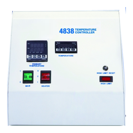
4838 Reactor Controller Component Summary Switches and Indicators Front side Back side 4838 Reactor Controller 115V 4838 Reactor Controller Protective Fuses and Relays The Heater Switch is a manual, three-position, illu- minated switch which controls the amount of power An instrument fuse is mounted on the back panel. -
Page 9: High Limit Reset
In either of these situations, The 4838 Controller has a number of fuses which the high limit reset will activate. The thermocouple are intended to be fi eld serviceable. -
Page 10: Instructions For The 4838 Reactor Controller
Output 1 on these controllers drives the heater. Out- PID groups put 2 is not used on the 4838 Controller. The control a. The primary temperature controller contains parameter can be set independently for this output. - Page 11 All of PID parameters in the group can be ob- tained from auto-tuning or they can be set The 4838 Controller has a programming feature manually. When manually entering PID values which allows more fl exibility when compared to set into a particular group, the SV for that group can point control.
- Page 12 4838 Reactor Controller Note: The fi rst SP_O used must be a higher Note: The program will attempt to hold the temperature than the current temperature temperature at the set point determined by (PV) or the program will not execute properly.
- Page 13 4838 Reactor Controller Appendix: sample programs A sample program to heat to 200 °C as fast a pos- A sample program to ramp from 25 °C to 250 °C in sible, hold for 2-hrs, and come back down as quickly...
- Page 14 Note: if the pressure transducer is not attached to the 4838 Controller, the High Limit Reset This module provides a digital read out for continu- may trip or show a fi xed but incorrect value.
- Page 15 When ordering this option separately or installed in To set the primary (non-latching) temperature limit, the 4838 Controller, always specify the reactor press the up or down arrow on the display. The set- with which it will be used so that a thermocouple of point value on the right will fl...
-
Page 16: Communication With Pc
1. Put the 552M CD into the CD-ROM. 2. Connect the A1925E4 communication cable between the comm port on the back of the 4838 Controller and an open USB slot on the PC. 3. The PC should open an "Install Hardware" wizard automatically when the cable is connected to the USB slot. - Page 17 REC fi le created in step 5. charting and datalogging program to run. The mod- ules on the 4838 may still be modifi ed manually at You may view the chart by clicking the recorder button.
-
Page 18: 4838 Factory Defaults
Temperature unit There are three broad categories of functions in the tP-H 800** Upper-limit range 4838 Controller modules. They are Regulation, Op- tP-L Lower-limit temperature eration, and Initial Settings. From the main screen, range Regulation mode is accessed by pressing the set... -
Page 19: Pressure Module
4838 Reactor Controller Pressure Module ** Set according to the following: Transducer tP-H for tP-H for tP-H for Press return key and release range - psi Operation Select 13.79 1.38 Comment Mode type/value 20.68 2.07 34.47 3.45 Run/Stop To be deter-... -
Page 20: Htm / Etlm Module
4838 Reactor Controller HTM / ETLM Module Press and hold down “SET” for 5-sec Operation Select Comment Press return key and release Mode type/value Operation Select InPt Input type Comment Mode type/value tPUn Temperature unit Run/Stop tP-H 800** Upper-limit temperature... -
Page 21: Appendix A: Controller Parameters
4838 Reactor Controller Appendix A: Controller Parameters Initial Setting Mode Press to advance Set input type Set temperature unit (Does not display when analog input) Set upper-limit of temperature range Set lower-limit of temperature range Select control mode Select heating/cooling control or dual loop output control... -
Page 22: Operation Mode
4838 Reactor Controller Operation Mode Press to advance key to set temperature set point Control setting RUN or STOP Start pattern setting Time setting) (PID program control and Decimal point position selection (except for B, S, R type inputs, all the other types can be set) -
Page 23: Regulation Mode
4838 Reactor Controller Regulation Mode Press to advance Auto-tuning (Available in PID control and RUN mode) 4 groups PID modes (n=0~3). When n=4, PID control is auto regulated. PD control offset setting (Available when PID control is ON and Ti=0, set the value of PdoF) -
Page 24: Parts List
4838 Reactor Controller Parts List Fuses Fuse Rating Part Number Instrument Fuse Fast acting, 1 Amp, 250VAC 139E6 Line Fuse(s) Fast acting, 20 Amp, 250VAC 2074E Warning: For continued protection against possible hazard, replace fuses with same type and rating of fuse. -
Page 25: Pressure Display Module (Pdm)
4838 Reactor Controller Pressure Display Module (PDM) Part number Description A1905E5 Pressure harness, 5-ft, covered A1905E Pressure harness, 10-ft, covered A1905E8 Pressure harness, 15-ft, covered A1905E3 Pressure harness, 20-ft, covered A1905E9 Pressure harness, 25-ft, covered A1905E7 Pressure harness, 30-ft, covered... -
Page 26: Hi-Temp Cut-Off Module (Htm)
4838 Reactor Controller Hi-Temp Cut-Off Module (HTM) or External Temperature Limit Module (ETLM) Part number Description A470E2 Thermocouple extension wire, 5-ft A470E4 Thermocouple extension wire, 10-ft A470E7 Thermocouple extension wire, 15-ft A470E5 Thermocouple extension wire, 20-ft A470E8 Thermocouple extension wire, 25-ft...
Need help?
Do you have a question about the 4838 and is the answer not in the manual?
Questions and answers