
Related Manuals for Nokia 2700c-2


Summary of Contents for Nokia 2700c-2
- Page 1 Nokia Customer Care Service Manual RM-561 (Nokia 2700c-2) Mobile Terminal Part No: 9215307 (Issue 1) COMPANY CONFIDENTIAL Copyright © 2009 Nokia. All rights reserved.
- Page 2 RM-561 Amendment Record Sheet Amendment Record Sheet Amendment No Date Inserted By Comments Original issue 04/2009 Jeff Zhao Page ii COMPANY CONFIDENTIAL Issue 1 Copyright © 2009 Nokia. All rights reserved.
- Page 3 Nokia operates a policy of continuous development. Nokia reserves the right to make changes and improvements to any of the products described in this document without prior notice. Under no circumstances shall Nokia be responsible for any loss of data or income or any special, incidental, consequential or indirect damages howsoever caused.
- Page 4 WCDMA networks and cause problems to 3G cellular phone communication in a wide area. • During testing never activate the GSM or WCDMA transmitter without a proper antenna load, otherwise GSM or WCDMA PA may be damaged. Page iv COMPANY CONFIDENTIAL Issue 1 Copyright © 2009 Nokia. All rights reserved.
- Page 5 Use only approved accessories and batteries. Do not connect incompatible products. CONNECTING TO OTHER DEVICES When connecting to any other device, read its user’s guide for detailed safety instructions. Do not connect incompatible products. Issue 1 COMPANY CONFIDENTIAL Page v Copyright © 2009 Nokia. All rights reserved.
- Page 6 All of the above suggestions apply equally to the product, battery, charger or any accessory. Page vi COMPANY CONFIDENTIAL Issue 1 Copyright © 2009 Nokia. All rights reserved.
- Page 7 RM-561 ESD protection ESD protection Nokia requires that service points have sufficient ESD protection (against static electricity) when servicing the phone. Any product of which the covers are removed must be handled with ESD protection. The SIM card can be replaced without ESD protection if the product is otherwise ready for use.
- Page 8 Batteries' performance is particularly limited in temperatures well below freezing. Do not dispose of batteries in a fire! Dispose of batteries according to local regulations (e.g. recycling). Do not dispose as household waste. Page viii COMPANY CONFIDENTIAL Issue 1 Copyright © 2009 Nokia. All rights reserved.
- Page 9 Our policy is of continuous development; details of all technical modifications will be included with service bulletins. While every endeavour has been made to ensure the accuracy of this document, some errors may exist. If any errors are found by the reader, NOKIA MOBILE PHONES Business Group should be notified in writing/e- mail. Please state: •...
- Page 10 RM-561 Company policy (This page left intentionally blank.) Page x COMPANY CONFIDENTIAL Issue 1 Copyright © 2009 Nokia. All rights reserved.
- Page 11 1 General information 2 Service Devices and Service Concepts 3 BB Troubleshooting and Manual Tuning Guide 4 RF troubleshooting 5 System Module 6 LCD flex bending instruction Glossary Issue 1 COMPANY CONFIDENTIAL Page xi Copyright © 2009 Nokia. All rights reserved.
- Page 12 RM-561 Nokia 2700c-2 Service Manual Structure (This page left intentionally blank.) Page xii COMPANY CONFIDENTIAL Issue 1 Copyright © 2009 Nokia. All rights reserved.
- Page 13 Nokia Customer Care 1 — General information Issue 1 COMPANY CONFIDENTIAL Page 1 –1 Copyright © 2009 Nokia. All rights reserved.
- Page 14 RM-561 General information (This page left intentionally blank.) Page 1 –2 COMPANY CONFIDENTIAL Issue 1 Copyright © 2009 Nokia. All rights reserved.
-
Page 15: Table Of Contents
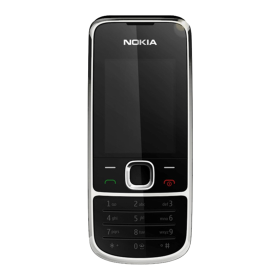
List of Tables Table 1 Battery and chargers ..........................1–6 Table 2 Headsets ..............................1–6 Table 3 Data cables ..............................1–7 List of Figures Figure 1 RM-561 (Nokia 2700c-2) product picture....................1–5 Issue 1 COMPANY CONFIDENTIAL Page 1 –3 Copyright © 2009 Nokia. All rights reserved. - Page 16 RM-561 General information (This page left intentionally blank.) Page 1 –4 COMPANY CONFIDENTIAL Issue 1 Copyright © 2009 Nokia. All rights reserved.
-
Page 17: Product Selection
RM-561 General information Product selection RM-561 (Nokia 2700c-2) is a GSM quad band phone, supporting GSM850/900/1800/1900 bands. Figure 1 RM-561 (Nokia 2700c-2) product picture Phone features Display and keypad features • 2” 240x320 pixel, 262k true colour display • 5-way , navi-key (2 soft-keys, call and end keys) Hardware features •... -
Page 18: User Interface And Software Features
• User Guide Table 1 Battery and chargers Type Name Note: This phone is charged through the smaller charger Nokia standard interface (2.mm plug). The standard 3.5mm standard charger can be used together with the CA-44 charger adapter. AC-3 Charger BL-5C... -
Page 19: Technical Specifications
3 hours Up to 12 days 244 hours Music 7.7 hours Note: Variation in operation times will occur depending on SIM card, network settings and usage. Issue 1 COMPANY CONFIDENTIAL Page 1 –7 Copyright © 2009 Nokia. All rights reserved. - Page 20 RM-561 General information (This page left intentionally blank.) Page 1 –8 COMPANY CONFIDENTIAL Issue 1 Copyright © 2009 Nokia. All rights reserved.
- Page 21 Nokia Customer Care 2 — Service Devices and Service Concepts Issue 1 COMPANY CONFIDENTIAL Page 2 –1 Copyright © 2009 Nokia. All rights reserved.
- Page 22 RM-561 Service Devices and Service Concepts (This page left intentionally blank.) Page 2 –2 COMPANY CONFIDENTIAL Issue 1 Copyright © 2009 Nokia. All rights reserved.
-
Page 23: Table Of Contents
..........................2–15 Figure 3 Basic flash concept with FPS-10......................2–16 Figure 4 CU-4 flash concept with FPS-10......................2–17 Figure 5 Module jig service concept ........................2–18 Issue 1 COMPANY CONFIDENTIAL Page 2 –3 Copyright © 2009 Nokia. All rights reserved. - Page 24 Figure 8 BB5 Basic Flash Concept with FPS-21, SS-62 ..................2–21 Figure 9 BB5 Basic RF & BB Tune Concept with FS-108..................2–22 Figure 10 BB5 Basic RF&BB Tune Concept with MJ-248 ................... 2–23 Page 2 –4 COMPANY CONFIDENTIAL Issue 1 Copyright © 2009 Nokia. All rights reserved.
-
Page 25: Service Devices
The table below gives a short overview of service devices that can be used for testing, error analysis, and repair of product RM-561. For the correct use of the service devices, and the best effort of workbench setup, please refer to various concepts. Issue 1 COMPANY CONFIDENTIAL Page 2 –5 Copyright © 2009 Nokia. All rights reserved. - Page 26 4 Connect an FBUS cable (if necessary). 5 Start Phoenix service software. Note: Phoenix enables CU-4 regulators via USB when it is started. Reconnecting the power supply requires a Phoenix restart. Page 2 –6 COMPANY CONFIDENTIAL Issue 1 Copyright © 2009 Nokia. All rights reserved.
- Page 27 FPS-10 sales package includes: • FPS-10 prommer • Power Supply with 5 country specific cords • USB cable Note: FPS-21 is substitute FPS-10 if FPS-10 has not been set Issue 1 COMPANY CONFIDENTIAL Page 2 –7 Copyright © 2009 Nokia. All rights reserved.
-
Page 28: Fps-21
FPS-21, the prommer needs to be opened by removing the front panel, rear panel and heatsink from the prommer body. Note: FPS-10 can be used for flashing instead of FPS-21 if necessary. Page 2 –8 COMPANY CONFIDENTIAL Issue 1 Copyright © 2009 Nokia. All rights reserved. - Page 29 SB-6 Bluetooth tester The SB-6 test box is a generic device to perform Bluetooth bit error rate testing and doing cordless FBUS connection via Bluetooth. Issue 1 COMPANY CONFIDENTIAL Page 2 –9 Copyright © 2009 Nokia. All rights reserved.
- Page 30 SRT-6 Opening tool SRT-6 is used to open phone covers. Note: The SRT-6 is included in the Nokia Standard Toolkit. SS-108 Peeling tool The peeling tool SS-108 is used to peel off the shielding. SS-203...
-
Page 31: Cables
RM-561. For the correct use of the service devices, and the best effort of workbench setup, please refer to various concepts. CA-101 Micro USB cable The CA-101 is a USB-to-microUSB data cable that allows connections between the PC and the phone. Issue 1 COMPANY CONFIDENTIAL Page 2 –11 Copyright © 2009 Nokia. All rights reserved. -
Page 32: Ca-112Ds
CA-35S is a power cable for connecting, for example, the FPS-10 flash prommer to the Point-Of-Sales (POS) flash adapter. CA-89DS Cable Provides VBAT and Flashbus connections to mobile device programming adapters. Page 2 –12 COMPANY CONFIDENTIAL Issue 1 Copyright © 2009 Nokia. All rights reserved. -
Page 33: Ca-99Ps
XCS-4 Modular cable XCS-4 is a shielded (one specially shielded conductor) modular cable for flashing and service purposes. Issue 1 COMPANY CONFIDENTIAL Page 2 –13 Copyright © 2009 Nokia. All rights reserved. - Page 34 The RF cable is used to connect, for example, a module repair jig to the RF measurement equipment. SMA to N-Connector approximately 610 mm. Attenuation for: • GSM850/900: 0.3+-0.1 dB • GSM1800/1900: 0.5+-0.1 dB • WLAN: 0.6+-0.1dB Page 2 –14 COMPANY CONFIDENTIAL Issue 1 Copyright © 2009 Nokia. All rights reserved.
-
Page 35: Service Concepts
Figure 2 POS flash concept Type Description Product specific tools BL-5C/ Battery BL-5CA Other tools FLS-5 POS flash dongle PC with Phoenix service software Cables CA-101 USB connectivity cable Issue 1 COMPANY CONFIDENTIAL Page 2 –15 Copyright © 2009 Nokia. All rights reserved. -
Page 36: Flash Concept With Fps-10
Other devices FPS-10 Flash prommer box PKD-1/PK-1 SW security device SS-46 Interface adapter PC with Phoenix service software Cables XCS-4 Modular cable CA-35S Power cable USB cable Page 2 –16 COMPANY CONFIDENTIAL Issue 1 Copyright © 2009 Nokia. All rights reserved. -
Page 37: Flash Concept With Fps-10
SW security device SS-62 Flash adapter base SX-4 Smart card PC with Phoenix service software Cables PCS-1 Power cable XCS-4 Modular cable Standard USB cable USB cable Issue 1 COMPANY CONFIDENTIAL Page 2 –17 Copyright © 2009 Nokia. All rights reserved. -
Page 38: Module Jig Service Concept
SW security device SX-4 Smart card PC with VPOS and Phoenix service software Measurement equipment Cables PCS-1 DC power cable XCS-4 Modular cable XRS-6 RF cable USB cable Page 2 –18 COMPANY CONFIDENTIAL Issue 1 Copyright © 2009 Nokia. All rights reserved. -
Page 39: Rf Testing Concept With Rf Coupler
SX-4 Smart card FPS-10 Flash prommer box PKD-1/PK-1 SW security device SS-62 Flash adapter base Measurement equipment PC with Phoenix service software Cables PCS-1 Power cable Issue 1 COMPANY CONFIDENTIAL Page 2 –19 Copyright © 2009 Nokia. All rights reserved. -
Page 40: Bb5 Basic Flash Concept With Fps-21, Ss-46
Modular cable XRS-6 RF cable GPIB control cable USB cable BB5 Basic Flash Concept with FPS-21, SS-46 Figure 7 BB5 Basic Flash Concept with FPS-21, SS-46 Page 2 –20 COMPANY CONFIDENTIAL Issue 1 Copyright © 2009 Nokia. All rights reserved. -
Page 41: Bb5 Basic Flash Concept With Fps-21, Ss-62
RM-561 Service Devices and Service Concepts BB5 Basic Flash Concept with FPS-21, SS-62 Figure 8 BB5 Basic Flash Concept with FPS-21, SS-62 Issue 1 COMPANY CONFIDENTIAL Page 2 –21 Copyright © 2009 Nokia. All rights reserved. -
Page 42: Bb5 Basic Rf & Bb Tune Concept With
RM-561 Service Devices and Service Concepts BB5 Basic RF & BB Tune Concept with FS-108 Figure 9 BB5 Basic RF & BB Tune Concept with FS-108 Page 2 –22 COMPANY CONFIDENTIAL Issue 1 Copyright © 2009 Nokia. All rights reserved. -
Page 43: Bb5 Basic Rf&Bb Tune Concept With Mj-248
RM-561 Service Devices and Service Concepts BB5 Basic RF&BB Tune Concept with MJ-248 Figure 10 BB5 Basic RF&BB Tune Concept with MJ-248 Issue 1 COMPANY CONFIDENTIAL Page 2 –23 Copyright © 2009 Nokia. All rights reserved. - Page 44 RM-561 Service Devices and Service Concepts (This page left intentionally blank.) Page 2 –24 COMPANY CONFIDENTIAL Issue 1 Copyright © 2009 Nokia. All rights reserved.
- Page 45 Nokia Customer Care 3 — BB Troubleshooting and Manual Tuning Guide Issue 1 COMPANY CONFIDENTIAL Page 3 –1 Copyright © 2009 Nokia. All rights reserved.
- Page 46 RM-561 BB Troubleshooting and Manual Tuning Guide (This page left intentionally blank.) Page 3 –2 COMPANY CONFIDENTIAL Issue 1 Copyright © 2009 Nokia. All rights reserved.
-
Page 47: List Of Figures
Figure 14 Differential output waveform of the Ext_in_IHF_out out loop measurement when speaker is connected..............................3–28 Figure 15 Single-ended output waveform of the HP_in_Ext_out loop when microphone is connected. 3–29 Issue 1 COMPANY CONFIDENTIAL Page 3 –3 Copyright © 2009 Nokia. All rights reserved. - Page 48 RM-561 BB Troubleshooting and Manual Tuning Guide (This page left intentionally blank.) Page 3 –4 COMPANY CONFIDENTIAL Issue 1 Copyright © 2009 Nokia. All rights reserved.
-
Page 49: Baseband Self Tests In Phoenix
Always start the troubleshooting procedure by running the Phoenix self tests. If a test fails, please follow the diagram below. Dead or jammed device troubleshooting. If the phone is dead and you cannot perform the self tests, go to Issue 1 COMPANY CONFIDENTIAL Page 3 –5 Copyright © 2009 Nokia. All rights reserved. - Page 50 RM-561 BB Troubleshooting and Manual Tuning Guide Troubleshooting flow Page 3 –6 COMPANY CONFIDENTIAL Issue 1 Copyright © 2009 Nokia. All rights reserved.
-
Page 51: Power And Charging Troubleshooting
RM-561 BB Troubleshooting and Manual Tuning Guide Power and charging troubleshooting Dead or jammed device troubleshooting Troubleshooting flow Issue 1 COMPANY CONFIDENTIAL Page 3 –7 Copyright © 2009 Nokia. All rights reserved. - Page 52 RM-561 BB Troubleshooting and Manual Tuning Guide Troubleshooting flow Page 3 –8 COMPANY CONFIDENTIAL Issue 1 Copyright © 2009 Nokia. All rights reserved.
-
Page 53: General Power Checking
RF active VREF AVILMA 1.35 RF reference VCORE BETTY 1.05 Combo memory 1.25 1.35 1.40 VOUT BETTY Accessory connected VSIM2 AVILMA Internal microphone Charging troubleshooting Troubleshooting flow Issue 1 COMPANY CONFIDENTIAL Page 3 –9 Copyright © 2009 Nokia. All rights reserved. - Page 54 RM-561 BB Troubleshooting and Manual Tuning Guide Page 3 –10 COMPANY CONFIDENTIAL Issue 1 Copyright © 2009 Nokia. All rights reserved.
-
Page 55: Interface Troubleshooting
RM-561 BB Troubleshooting and Manual Tuning Guide Interface troubleshooting Flash programming fault troubleshooting Part 1 Issue 1 COMPANY CONFIDENTIAL Page 3 –11 Copyright © 2009 Nokia. All rights reserved. - Page 56 RM-561 BB Troubleshooting and Manual Tuning Guide Part 2 Figure 11 Flashing pic 1. Take single trig measurement for the rise of the BSI signal. Page 3 –12 COMPANY CONFIDENTIAL Issue 1 Copyright © 2009 Nokia. All rights reserved.
- Page 57 RM-561 BB Troubleshooting and Manual Tuning Guide Figure 12 Flashing pic 2. Take single trig measurement for the rise of the BSI signal. Issue 1 COMPANY CONFIDENTIAL Page 3 –13 Copyright © 2009 Nokia. All rights reserved.
-
Page 58: Combo Memory Troubleshooting
RM-561 BB Troubleshooting and Manual Tuning Guide Combo memory troubleshooting Troubleshooting flow Page 3 –14 COMPANY CONFIDENTIAL Issue 1 Copyright © 2009 Nokia. All rights reserved. -
Page 59: Usb Interface Troubleshooting
RM-561 BB Troubleshooting and Manual Tuning Guide USB interface troubleshooting Troubleshooting flow Issue 1 COMPANY CONFIDENTIAL Page 3 –15 Copyright © 2009 Nokia. All rights reserved. -
Page 60: Sim Card Troubleshooting
RM-561 BB Troubleshooting and Manual Tuning Guide SIM card troubleshooting Troubleshooting flow Page 3 –16 COMPANY CONFIDENTIAL Issue 1 Copyright © 2009 Nokia. All rights reserved. - Page 61 RM-561 BB Troubleshooting and Manual Tuning Guide Issue 1 COMPANY CONFIDENTIAL Page 3 –17 Copyright © 2009 Nokia. All rights reserved.
-
Page 62: User Interface Troubleshooting
• Malfunction of several keys at the same time; this happens when one or more rows or columns in the key matrix are failing (shortcut or open connection). If the failure mode is not clear, start with the Keyboard test in Phoenix. Page 3 –18 COMPANY CONFIDENTIAL Issue 1 Copyright © 2009 Nokia. All rights reserved. - Page 63 RM-561 BB Troubleshooting and Manual Tuning Guide Troubleshooting flow Issue 1 COMPANY CONFIDENTIAL Page 3 –19 Copyright © 2009 Nokia. All rights reserved.
-
Page 64: Display Module Troubleshooting
Total Combine Not allowed. d defect Two single dot defects that are within 5 mm of each other should counts be interpreted as combined dot defect. Page 3 –20 COMPANY CONFIDENTIAL Issue 1 Copyright © 2009 Nokia. All rights reserved. -
Page 65: Display Troubleshooting
RM-561 BB Troubleshooting and Manual Tuning Guide Display troubleshooting Troubleshooting flow Issue 1 COMPANY CONFIDENTIAL Page 3 –21 Copyright © 2009 Nokia. All rights reserved. -
Page 66: Keyboard Backlight Troubleshooting
RM-561 BB Troubleshooting and Manual Tuning Guide Keyboard backlight troubleshooting Troubleshooting flow Page 3 –22 COMPANY CONFIDENTIAL Issue 1 Copyright © 2009 Nokia. All rights reserved. -
Page 67: Sd Card Troubleshooting
RM-561 BB Troubleshooting and Manual Tuning Guide SD card troubleshooting Troubleshooting flow Issue 1 COMPANY CONFIDENTIAL Page 3 –23 Copyright © 2009 Nokia. All rights reserved. -
Page 68: Camera Troubleshooting
RM-561 BB Troubleshooting and Manual Tuning Guide Camera troubleshooting Camera troubleshooting Troubleshooting flow Page 3 –24 COMPANY CONFIDENTIAL Issue 1 Copyright © 2009 Nokia. All rights reserved. - Page 69 RM-561 BB Troubleshooting and Manual Tuning Guide Issue 1 COMPANY CONFIDENTIAL Page 3 –25 Copyright © 2009 Nokia. All rights reserved.
-
Page 70: Audio Troubleshooting
Earpiece, internal microphone and speaker are in place during measurement. Applying a headset accessory during measurement causes a significant drop in measured quantities. The gain values presented in the table apply for a differential output vs. single-ended/differential input. Page 3 –26 COMPANY CONFIDENTIAL Issue 1 Copyright © 2009 Nokia. All rights reserved. - Page 71 (OUT/GND) HSEAR R N and GND HSEAR P, HSEAR N and GND HSEAR R P, HSEAR R N and GND HSEAR P, HSEAR N and GND Issue 1 COMPANY CONFIDENTIAL Page 3 –27 Copyright © 2009 Nokia. All rights reserved.
- Page 72 If a special low-pass filter designed for measuring digital amplifiers is unavailable, the measurement must be performed with a current probe and the input signal frequency must be 2kHz. Figure 14 Differential output waveform of the Ext_in_IHF_out out loop measurement when speaker is connected. Page 3 –28 COMPANY CONFIDENTIAL Issue 1 Copyright © 2009 Nokia. All rights reserved.
- Page 73 RM-561 BB Troubleshooting and Manual Tuning Guide Figure 15 Single-ended output waveform of the HP_in_Ext_out loop when microphone is connected. Issue 1 COMPANY CONFIDENTIAL Page 3 –29 Copyright © 2009 Nokia. All rights reserved.
-
Page 74: Internal Earpiece Troubleshooting
RM-561 BB Troubleshooting and Manual Tuning Guide Internal earpiece troubleshooting Troubleshooting flow Page 3 –30 COMPANY CONFIDENTIAL Issue 1 Copyright © 2009 Nokia. All rights reserved. -
Page 75: Internal Microphone Troubleshooting
RM-561 BB Troubleshooting and Manual Tuning Guide Internal microphone troubleshooting Troubleshooting flow Issue 1 COMPANY CONFIDENTIAL Page 3 –31 Copyright © 2009 Nokia. All rights reserved. -
Page 76: Internal Handsfree (Ihf) Troubleshooting
RM-561 BB Troubleshooting and Manual Tuning Guide Internal handsfree (IHF) troubleshooting Troubleshooting flow Page 3 –32 COMPANY CONFIDENTIAL Issue 1 Copyright © 2009 Nokia. All rights reserved. -
Page 77: External Earpiece Troubleshooting
RM-561 BB Troubleshooting and Manual Tuning Guide External earpiece troubleshooting Troubleshooting flow Issue 1 COMPANY CONFIDENTIAL Page 3 –33 Copyright © 2009 Nokia. All rights reserved. -
Page 78: External Microphone Troubleshooting
RM-561 BB Troubleshooting and Manual Tuning Guide External microphone troubleshooting Troubleshooting flow Page 3 –34 COMPANY CONFIDENTIAL Issue 1 Copyright © 2009 Nokia. All rights reserved. -
Page 79: Vibra Troubleshooting
RM-561 BB Troubleshooting and Manual Tuning Guide Vibra troubleshooting Troubleshooting flow Issue 1 COMPANY CONFIDENTIAL Page 3 –35 Copyright © 2009 Nokia. All rights reserved. -
Page 80: Baseband Manual Tuning Guide
Note: USB flashing does not work for a dead BB5 phone. • Create a request file. • Send the file to Nokia by e-mail. Use the following addresses depending on your location: • APAC: sydney.service@nokia.com • CHINA: repair.ams@nokia.com • E&A: salo.repair@nokia.com •... - Page 81 Flash Type must be set to Phone as Manufactured. To continue, click Start. Progress bars and messages on the screen show actions during phone programming, please wait. Issue 1 COMPANY CONFIDENTIAL Page 3 –37 Copyright © 2009 Nokia. All rights reserved.
- Page 82 Phoenix , choose File→Scan Product . To connect the phone with ii Choose Tools→Certificate Restore . iii To choose a location for the request file, click Browse. Page 3 –38 COMPANY CONFIDENTIAL Issue 1 Copyright © 2009 Nokia. All rights reserved.
- Page 83 Request file, click Start. To create the vi When the file for certificate restore has been created, send it to Nokia as an e-mail attachment. 3. Restore certificate. For this procedure, you must supply +12 V to CU-4 from an external power supply.
- Page 84 To write the file to phone, click Start. Next actions Phoenix tuning functions. After a successful rewrite, you must retune the phone completely by using Important: Perform all tunings: RF, BB, and UI. Page 3 –40 COMPANY CONFIDENTIAL Issue 1 Copyright © 2009 Nokia. All rights reserved.
-
Page 85: Energy Management Calibration
Write and/or repeat the procedure again. Energy Management Calibration window. 10. To end the procedure, close the Issue 1 COMPANY CONFIDENTIAL Page 3 –41 Copyright © 2009 Nokia. All rights reserved. - Page 86 RM-561 BB Troubleshooting and Manual Tuning Guide (This page left intentionally blank.) Page 3 –42 COMPANY CONFIDENTIAL Issue 1 Copyright © 2009 Nokia. All rights reserved.
- Page 87 Nokia Customer Care 4 — RF troubleshooting Issue 1 COMPANY CONFIDENTIAL Page 4 –1 Copyright © 2009 Nokia. All rights reserved.
- Page 88 RM-561 RF troubleshooting (This page left intentionally blank.) Page 4 –2 COMPANY CONFIDENTIAL Issue 1 Copyright © 2009 Nokia. All rights reserved.
- Page 89 Figure 21 Settings: Time 1ns/d + 0.3Vpp/d ...................... 4–12 Figure 22 Frequency ~ 100kHz........................... 4–14 Figure 23 Typical readings ..........................4–17 Figure 24 Troubleshooting diagram: Bluetooth ....................4–18 Issue 1 COMPANY CONFIDENTIAL Page 4 –3 Copyright © 2009 Nokia. All rights reserved.
- Page 90 RM-561 RF troubleshooting (This page left intentionally blank.) Page 4 –4 COMPANY CONFIDENTIAL Issue 1 Copyright © 2009 Nokia. All rights reserved.
-
Page 91: General Rf Troubleshooting
RF shielded environment, testing at frequencies of nearby base stations should be avoided. Level of repair The scope of this guideline is to enable repairs at key-component level. Please refer to the troubleshooting instructions for further information. Issue 1 COMPANY CONFIDENTIAL Page 4 –5 Copyright © 2009 Nokia. All rights reserved. -
Page 92: Rf Key Components
• Cables: XRS-6 (RF cable), USB cable, GBIP cable and DAU-9S • Signal analyser (TX), signal generator (RX) and RF-splitter or one device including all. Figure 17 Auto tuning concept with CMU200 Page 4 –6 COMPANY CONFIDENTIAL Issue 1 Copyright © 2009 Nokia. All rights reserved. -
Page 93: General Voltage Checking
Signal name Test point Voltage (all bands) Vbat at N1002 (FEM) J2903 3.0-4.7 V Vbat at N1001 (Transceiver) C2070 3.0-4.7 V VCCXO supply C2213 2.4-2.6 V Issue 1 COMPANY CONFIDENTIAL Page 4 –7 Copyright © 2009 Nokia. All rights reserved. -
Page 94: Selftest Troubleshooting
Testing→GSM→RF Controls→ RX and then press Stop. Context Note: The RF connector should be terminated to 50 Ohms or connected to the antenna. Check this carefully before performing the self tests. Page 4 –8 COMPANY CONFIDENTIAL Issue 1 Copyright © 2009 Nokia. All rights reserved. - Page 95 RF troubleshootings. 3. If Fatal, press Details to see error codes Detailed . Error codes will now show up in the right most column marked Issue 1 COMPANY CONFIDENTIAL Page 4 –9 Copyright © 2009 Nokia. All rights reserved.
-
Page 96: Fatal Selftests Troubleshooting
If a self test is fatal, check the Details→Error code and follow the instructions below. Note: If ST_CDSP_RF_BB_IF_TEST is fatal, the other self tests will also be fatal. Always start troubleshooting ST_CDSP_RF_BB_IF_TEST. Page 4 –10 COMPANY CONFIDENTIAL Issue 1 Copyright © 2009 Nokia. All rights reserved. - Page 97 Figure 19 Testpoints used after fatal self tests ST_CDSP_RF_BB_IF_TEST is fatal This test is checking the communication between baseband and RF. It will show in what part the problem is located. Issue 1 COMPANY CONFIDENTIAL Page 4 –11 Copyright © 2009 Nokia. All rights reserved.
- Page 98 1 J2210 TXBB_CLK (Ch1) [4] 2 J2212 TXBB_DATA (Ch2) [5] 3 J2902 STROBE (Ch3) [6] The result should look like this: Figure 21 Settings: Time 1ns/d + 0.3Vpp/d Page 4 –12 COMPANY CONFIDENTIAL Issue 1 Copyright © 2009 Nokia. All rights reserved.
- Page 99 This test is checking the analogue RX communication between baseband and RF. Error code Test Action ST_FIMRCAL_FAIL (0x00, 0x40) Replace N1001 or combination (0x00, 0x50) and (0x00, 0x60) Issue 1 COMPANY CONFIDENTIAL Page 4 –13 Copyright © 2009 Nokia. All rights reserved.
-
Page 100: Receiver Troubleshooting
Introduction to receiver (RX) troubleshooting RX can be tested by making a phone call or in local mode. For the local mode testing, use Phoenix service software. Page 4 –14 COMPANY CONFIDENTIAL Issue 1 Copyright © 2009 Nokia. All rights reserved. -
Page 101: Gsm Rx Chain Activation For Manual Measurements/Gsm Rssi Measurement
Now select the measuring mode to the signal generator level. Next actions RSSI-reading AND TX troubleshooting is failing: replace N1002. TX is OK and RX is failing: replace N1001. Issue 1 COMPANY CONFIDENTIAL Page 4 –15 Copyright © 2009 Nokia. All rights reserved. -
Page 102: Transmitter Troubleshooting
GSM transmitter troubleshooting Steps 1. Set the phone to local mode. 2. Activate RF controls in Phoenix (Testing→GSM→Rf Controls ). Make settings as shown in the picture: Page 4 –16 COMPANY CONFIDENTIAL Issue 1 Copyright © 2009 Nokia. All rights reserved. - Page 103 RF troubleshooting 3. Check the basic TX parameters (i.e. power, phase error, modulation and switching spectrum), using a communication analyser (for example CMU200). Figure 23 Typical readings Issue 1 COMPANY CONFIDENTIAL Page 4 –17 Copyright © 2009 Nokia. All rights reserved.
-
Page 104: Bluetooth And Fm Radio Troubleshooting
If you want to troubleshoot the other bands, change band with RF controls and set the communication analyzer accordingly. Bluetooth and FM radio troubleshooting Bluetooth troubleshooting Troubleshooting flow Figure 24 Troubleshooting diagram: Bluetooth Page 4 –18 COMPANY CONFIDENTIAL Issue 1 Copyright © 2009 Nokia. All rights reserved. -
Page 105: Fm Radio Troubleshooting
RM-561 RF troubleshooting FM radio troubleshooting Troubleshooting flow Issue 1 COMPANY CONFIDENTIAL Page 4 –19 Copyright © 2009 Nokia. All rights reserved. - Page 106 RM-561 RF troubleshooting (This page left intentionally blank.) Page 4 –20 COMPANY CONFIDENTIAL Issue 1 Copyright © 2009 Nokia. All rights reserved.
- Page 107 Nokia Customer Care 5 — System Module Issue 1 COMPANY CONFIDENTIAL Page 5 –1 Copyright © 2009 Nokia. All rights reserved.
- Page 108 RM-561 System Module (This page left intentionally blank.) Page 5 –2 COMPANY CONFIDENTIAL Issue 1 Copyright © 2009 Nokia. All rights reserved.
- Page 109 Figure 25 Battery pin order ...........................5–7 Figure 26 Battery connector..........................5–8 Figure 27 SIM interface ............................5–10 Figure 28 Audio block diagram.......................... 5–12 Figure 29 Bluetooth interface ..........................5–15 Issue 1 COMPANY CONFIDENTIAL Page 5 –3 Copyright © 2009 Nokia. All rights reserved.
- Page 110 RM-561 System Module (This page left intentionally blank.) Page 5 –4 COMPANY CONFIDENTIAL Issue 1 Copyright © 2009 Nokia. All rights reserved.
-
Page 111: Introduction
N6000 Battery BL-5C 1020 mAh/BL-5CA 700 mAh Battery connector Lynx interface X2070 µUSB connector For data, support USB full speed AV flex: X2002 Key component placement Issue 1 COMPANY CONFIDENTIAL Page 5 –5 Copyright © 2009 Nokia. All rights reserved. - Page 112 RM-561 System Module System module block diagram Board and module connections Page 5 –6 COMPANY CONFIDENTIAL Issue 1 Copyright © 2009 Nokia. All rights reserved.
-
Page 113: Energy Management
BSI and GND where the BSI line is used to recognize the battery capacity. This is done by means of an internal battery pull down resistor. Figure 25 Battery pin order The battery temperature can be measured from the UI flex. Issue 1 COMPANY CONFIDENTIAL Page 5 –7 Copyright © 2009 Nokia. All rights reserved. -
Page 114: Normal And Extreme Voltages
2.1 ± 0.1 Off to on Vmstr- 1.9 ± 0.1 On to off SW Shutdown Voltages Sw shutdown 3.106 In call Sw shutdown In idle Min Operating Voltage Page 5 –8 COMPANY CONFIDENTIAL Issue 1 Copyright © 2009 Nokia. All rights reserved. -
Page 115: Power Key And System Power-Up
Hot swap is supported, which means that USB devices may be plugged in/out at any time. This phone is provided with a specific connector for µUSB. Issue 1 COMPANY CONFIDENTIAL Page 5 –9 Copyright © 2009 Nokia. All rights reserved. -
Page 116: Sim Interface
SIM card is inserted, and if the card does not response to the ATR a 3 V interface voltage is used. µSD card interface The µSD card is connected to the engine by an external level shifter and ESD protection filter. Supplied voltages: Page 5 –10 COMPANY CONFIDENTIAL Issue 1 Copyright © 2009 Nokia. All rights reserved. -
Page 117: User Interface
ROW4 Backlight and illumination There is backlight illuminating for the display consisting of 2 LEDs. The keypad is side lit by 4 LEDs with film lightguide. Issue 1 COMPANY CONFIDENTIAL Page 5 –11 Copyright © 2009 Nokia. All rights reserved. -
Page 118: Audio Concept
A connected male connector is detected on pin 6 (PLUG_DET). Note: Only use an approved cable for connecting to the AV connector ( e.g. headset HS-125). Page 5 –12 COMPANY CONFIDENTIAL Issue 1 Copyright © 2009 Nokia. All rights reserved. -
Page 119: Rf Description
An analogue signal is received by the phone's antenna. The signal is converted to a digital signal and is then transferred further to the baseband (eg. to the earpiece). The receiver functions are implemented in the RF ASIC. Issue 1 COMPANY CONFIDENTIAL Page 5 –13 Copyright © 2009 Nokia. All rights reserved. -
Page 120: Transmitter (Tx)
Bluetooth provides a fully digital link for communication between a master unit (the phone) and one or more slave units (e.g. a wireless headset). Data and control interface for a low power RF module is provided by the module. Page 5 –14 COMPANY CONFIDENTIAL Issue 1 Copyright © 2009 Nokia. All rights reserved. -
Page 121: Technical Specifications
EGSM900: +5 … +32.4 dBm GSM1800: +0 … +30.3 dBm GSM1900: +0 ... +30.3 dBm Number of RF channels GSM850: 124 EGSM900: 172 GSM1800: 375 GSM1900: 300 Issue 1 COMPANY CONFIDENTIAL Page 5 –15 Copyright © 2009 Nokia. All rights reserved. -
Page 122: Environmental Conditions
Condensed or dripping water may cause intermittent malfunctions. Protection against dripping water has to be implemented in (enclosure) mechanics. Continuous dampness will cause permanent damage to the module. Page 5 –16 COMPANY CONFIDENTIAL Issue 1 Copyright © 2009 Nokia. All rights reserved. - Page 123 Nokia Customer Care 6 — LCD flex bending instruction Issue 1 COMPANY CONFIDENTIAL Page 6 –1 Copyright © 2009 Nokia. All rights reserved.
- Page 124 RM-561 LCD flex bending instruction (This page left intentionally blank.) Page 6 –2 COMPANY CONFIDENTIAL Issue 1 Copyright © 2009 Nokia. All rights reserved.
- Page 125 RM-561 LCD flex bending instruction Table of Contents Steps of LCD assembling ............................6–5 Mating/unmating method of B to B connector ....................6–6 Issue 1 COMPANY CONFIDENTIAL Page 6 –3 Copyright © 2009 Nokia. All rights reserved.
- Page 126 RM-561 LCD flex bending instruction (This page left intentionally blank.) Page 6 –4 COMPANY CONFIDENTIAL Issue 1 Copyright © 2009 Nokia. All rights reserved.
- Page 127 RM-561 LCD flex bending instruction Steps of LCD assembling Press on connector first then S-bend flex frontad. Issue 1 COMPANY CONFIDENTIAL Page 6 –5 Copyright © 2009 Nokia. All rights reserved.
- Page 128 RM-561 LCD flex bending instruction Mating/unmating method of B to B connector Page 6 –6 COMPANY CONFIDENTIAL Issue 1 Copyright © 2009 Nokia. All rights reserved.
- Page 129 Nokia Customer Care Glossary Issue 1 COMPANY CONFIDENTIAL Page Glossary–1 Copyright © 2009 Nokia. All rights reserved.
- Page 130 RM-561 Glossary (This page left intentionally blank.) Page Glossary–2 COMPANY CONFIDENTIAL Issue 1 Copyright © 2009 Nokia. All rights reserved.
- Page 131 Clock Timing Sleep and interrupt block of Tiku Continuous wave D/A-converter Digital-to-analogue converter Digital-to-analogue converter Digital Battery Interface DBus DSP controlled serial bus connected between UPP_WD2 and Helgo Issue 1 COMPANY CONFIDENTIAL Page Glossary–3 Copyright © 2009 Nokia. All rights reserved.
- Page 132 High speed circuit switched data (data transmission connection faster than GSM) Hardware Input/Output IBAT Battery current Integrated circuit ICHAR Charger current Interface Integrated hands free IMEI International Mobile Equipment Identity Infrared Page Glossary–4 COMPANY CONFIDENTIAL Issue 1 Copyright © 2009 Nokia. All rights reserved.
- Page 133 Phase locked loop (Phone) Permanent memory General Purpose IO (PIO), USARTS and Pulse Width Modulators PURX Power-up reset Printed Wiring Board Pulse width modulation RC-filter Resistance-Capacitance filter Radio Frequency Issue 1 COMPANY CONFIDENTIAL Page Glossary–5 Copyright © 2009 Nokia. All rights reserved.
- Page 134 UPnP Universal Plug and Play Universal Phone Processor UPP_WD2 Communicator version of DCT4 system ASIC Universal Serial Bus VBAT Battery voltage VCHAR Charger voltage Voltage controlled oscillator Page Glossary–6 COMPANY CONFIDENTIAL Issue 1 Copyright © 2009 Nokia. All rights reserved.
- Page 135 Wideband code division multiple access Watchdog WLAN Wireless local area network XHTML Extensible hypertext markup language Zocus Current sensor (used to monitor the current flow to and from the battery) Issue 1 COMPANY CONFIDENTIAL Page Glossary–7 Copyright © 2009 Nokia. All rights reserved.
- Page 136 RM-561 Glossary (This page left intentionally blank.) Page Glossary–8 COMPANY CONFIDENTIAL Issue 1 Copyright © 2009 Nokia. All rights reserved.
Need help?
Do you have a question about the 2700c-2 and is the answer not in the manual?
Questions and answers