Advertisement
The water protection switch WSS 1 detects leaks, alerts the user acoustically and visually, and shuts off the power and water supply. Areas of application include:
- Detection of defects in washing machines, dishwashers or hot water boilers.
- Alarm for incoming high water.
- Additional fuse for water level or float switch.
Target group, qualification
Qualified electricians are trained for the specific scope of their work and know the relevant standards and regulations. They can perform work on electrical systems and independently recognise and avoid potential dangers based on their training and experience.
Users have read these operating instructions and are aware of the possible dangers associated with improper behaviour.
Safety
Depiction used

Possibility of serious bodily injury or death
- Preventive measures
Instructions for use / useful information
Intended use
The water protection switch is intended for use in the private and commercial sector,
- to detect leakages of electro-conductive, non-aggressive liquids with a water sensor,
- alert users about such,
- turn off the connected power and water supply with the solenoid valve.
Any other or extended use of the water protection switch that is outside the operating parameters is improper.
Modifications are prohibited.
Electricity risks
- Comply with the operating parameters, see Technical data.
- Inspect live cables and lines for insulation faults and breaks before use.
- Do not touch any damaged lines.
- Unplug the universal temperature switch before working on it.
- Do not open the water protection switch.
- Do not operate the water protection switch if:
- the water circuit breaker, solenoid valve, water sensor, or cable are damaged,
- the water protection switch has been exposed to extreme moisture,
- in case of moisture ingress.
Provisions for persons with limited abilities
- Persons with limited physical, sensory or mental abilities or persons with insufficient experience or knowledge must neither install the water protection switch nor connect it electrically.
- There is a risk of choking through plastic bags and if swallowed. Keep children away from the packaging material.
- Children underestimate the danger of electrical appliances. Do not leave children unsupervised with the water protection switch.
Behaviour in case of an emergency
De-energise the water protection switch and connected loads from the power supply if there is a:
- risk of injury,
- ƒrisk of damaging the water protection switch or any other objects.
In the event of an accident, take immediate action and, if required, call the EU-wide emergency number 112.
Technical data
| Ambient temperature | 0...+50°C |
| Relative humidity | < 80% |
| Dimensions WSS 1 length, width, height | 98 mm, 60 mm, 41 mm |
| Dimensions WSS 1V Length, width, height | 84 mm, 54 mm, 40 mm |
| Dimensions water sensor length, width, height | 75 mm, 30 mm, 8 mm |
| Weight WSS 1 | 157 g |
| Weight WSS 1V | 315 g |
| Weight water sensor | 56 g |
| Operating voltage | 230 V AC |
| Power consumption | approx. 5.0 W |
| Power consumption standby | approx. 0.5 W |
| Switching capacity (resistive load) | max. 3680 W |
| Trigger sensitivity | ≈100 kOhm |
| Protection class | IP20 |
| Water sensor connection | 3.5 mm |
| Solenoid valve connection | 2.5 mm |
| Alarm volume | approx. 80 dB |
| Water connection | G3/4 |
| Cable lengths | approx. 2 m |

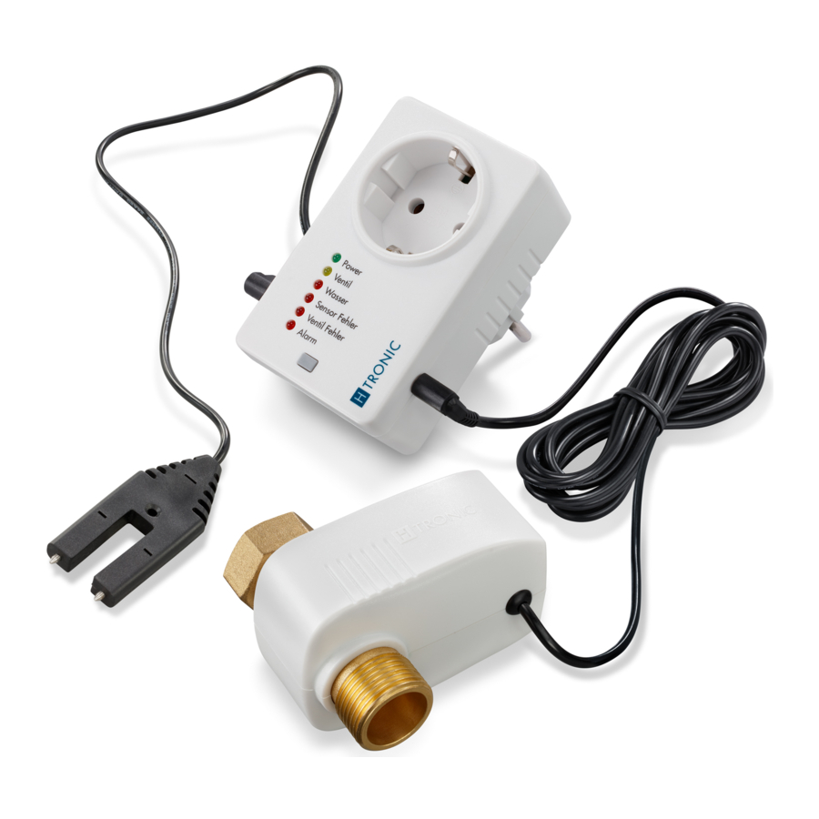
| Item | Designation |
| 1 | Input water sensor |
| 2 | Solenoid valve input |
Scope of delivery
- Water protection switch WSS 1
- Solenoid valve WSS 1V
- Water sensor
Installation
Prerequisites:
- The operating location of the water protection switch must be protected from moisture, dust, and direct sunlight.
- A free, easily accessible 230 V protective contact socket is available.
- You have given the water protection switch for at least 2 hours to adjust to the ambient conditions at the operating site.
- The water supply is turned off.
Tripping due to loose cables possible.
- Keep escape routes and stairways clear.
- Lay cables so that tripping and stepping on them is prevented, e.g. in a cable duct.
Never connect several water protection switchs to each other.
How to mount the water protection switch:
- Plug the water protection switch into a 230 V socket.

The "Power" LED lights up. - Plug the cable of the water sensor into the left-hand socket of the water protection switch (item 1, Figure 1).

- Lay the cable so that the metal pins of the water sensor pointing downwards have a distance of 0.5 mm to the floor, under consideration of slopes.
- Fasten the water sensor through the mounting hole with appropriate fastening material, e.g. with a screw. ¨ The water sensor is mounted.
- Plug the cable of the solenoid valve into the right-hand socket of the water protection switch (item 2, Figure 1).
- Lay the cable of the solenoid valve to the place of use.


Only skilled users are allowed to install the solenoid valve between the unit and the water supply.
Tighten the union nuts manually. Do not use any tools. The union nuts may be damaged by this.
Have the water supply installed by a professional if in doubt.

| Item | Designation |
| 1 | Water supply |
| 2 | Prefilter |
| 3 | Union nut solenoid valve |
| 4 | Solenoid valve |
| 5 | Seal |
| 6 | Union nut water hose |
| 7 | Water hose |
- Screw the solenoid valve (item 4, Figure 4) incl. pre-filter (item 2, Figure 4) with the union nut (item 3, Figure 4) to the water supply (item 1, Figure 4).
- Screw the hose of the device (item 7, Figure 4) to the other side of the solenoid valve using the union nut (item 6, Figure 4) and a suitable seal (item 5, Figure 4).
The solenoid valve is mounted.
- You have mounted the water protection switch.
Note
When switched, the solenoid valve will heat up to a safe temperature. This is due to technical reasons and is safe for use.
Commissioning
Display

| Item | Colour | Designation |
| 1 | green | "Power" LED |
| 2 | orange | "Valve" LED |
| 3 | red | "Water" LED |
| 4 | red | "Sensor error" LED |
| 5 | red | "Valve error" LED |
| 6 | red | "Alarm" LED |
| 7 | grey | Button |
Device connection
Do not operate any safety-relevant applications on the water protection switch.
For connecting a device to the water protection switch:
- Open the water supply at the faucet.
- Check the tightness of the connection.
- Push the button on the water protection switch (item 7, Figure 5).
- The "Valve" LED lights up (item 2, Figure 5).
- The integrated socket on the water protection switch is turned on.
- The solenoid valve is open.
- Plug the power cable of the device into the socket of the water protection switch.


You have connected the device to the water protection switch.
The power and water supply to the unit are not interrupted while there is no leakage or fault.
Errors
Water sensor detects water:
- Alarm sounds.
- The "Water" LED lights up and "Alarm" flashes.
- The integrated socket on the water protection switch is turned off.
- The "Valve" LED goes out. ƒ Stomach valve is closed.
Remedy:
- Eliminate the detected wetness.
The "Water" LED goes out. - Push the button (item 7, Figure 5).
The alarm is reset. - Push the button again.
The "Valve" LED lights up.
The integrated socket on the water protection switch is turned on.
The solenoid valve is open.
Еhe error has been remedied.
No water sensor connected:
- Alarm sounds.
- "Sensor error" and "Alarm" LEDs flash.
- The integrated socket on the water protection switch is turned off.
- The "Valve" LED goes out. ƒ Stomach valve is closed.
Remedy:
- Plug the cable of the water sensor into the provided socket of the water protection switch (item 1, Figure 1). ¨ The alarm is reset.
- Push the button (item 7, Figure 5).
The integrated socket on the water protection switch is turned on.
The "Valve" LED lights up.
The solenoid valve is open.
The error has been remedied.
If this process cannot be performed, there may be a defect in the connected water sensor. Replace it if necessary. Only use original spare parts.
No solenoid valve connected:
- Alarm sounds.
- The "Valve error" and "Alarm" LEDs flash.
- The integrated socket on the water protection switch is turned off.
- The "Valve" LED goes out.
- The solenoid valve is closed.
Remedy:
- Plug the cable of the solenoid valve into the socket of the water protection switch (item 2, Figure 1). ¨ The alarm is reset.
- Push the button (item 7, Figure 5).
The integrated socket on the water protection switch is turned on.
The "Valve" LED lights up.
The solenoid valve is open.
The error has been remedied.
If this process cannot be performed, there may be a defect in the connected solenoid valve. Replace it if necessary. Only use original spare parts.
Extension
For powerful 230 V AC devices whose switching capacity briefly exceeds the permitted 3680 W upon activation, use the water protection switch together with the inrush current limiter SCL 3680 (part no.:1114730)
Maintenance and care
Monthly inspections
- Check for leaks in the solenoid valve connections at least once a month. Re-tighten the screw caps if they detect this.
- Manually trigger the alarm of the water protection switch at least once a month.
Check both as follows:
- Use a dry cloth on the water connections of the solenoid valve to determine if it is getting wet.
- If not, you have checked the tightness.
- If it does, tighten the screw caps and check the pre-filter including the seal for damage.
- Touch both contacts of the water sensor with a metal object, e.g. a screw.
The error "Water sensor detects water" occurs.
You have checked the solenoid valve and water sensor.
If this process cannot be performed, there may be a defect at the water protection switch in the connected solenoid valve water protection switch or water sensor. Replace them if necessary. Only use original spare parts.
Cleaning
Possibility of electric shock due to incorrect cleaning.
- Disconnect the water protection switch from the socket before cleaning.
- Never immerse the water protection switch in water.
Clean the tips of the water sensor with a soft mist-damp cloth at least monthly.

Clean the pre-filter of the solenoid valve at least once a year under running water, depending on the degree of contamination.
Decommissioning
Prerequisites:
- The power and water supplies are shut off.
- The device has been unplugged from the water protection switch.
How to disassemble the water protection switch:
- Disconnect the water protection switch from the socket.
- Unscrew the hose of the device from the solenoid valve.
- Unscrew the solenoid valve with the union nut from the water supply.
- Disconnect the solenoid valve plugs from the water protection switch.
- Disconnect the cable routing of the solenoid valve.
The solenoid valve has been disassembled. - Loosen the fastening of the water sensor.
- Disconnect the cable routing of the water sensor.
- Disconnect the water sensor plugs from the water protection switch.
The water sensor is disassembled. - The water protection switch has been disassembled.
Documents / ResourcesDownload manual
Here you can download full pdf version of manual, it may contain additional safety instructions, warranty information, FCC rules, etc.
Download H-Tronic WSS - Water Protection Switch Operating Guide
Advertisement


Need help?
Do you have a question about the WSS 1 and is the answer not in the manual?
Questions and answers