Powrmatic MC200 User, Installation & Servicing Manual
Hide thumbs
Also See for MC200:
- Installation and setting instructions manual (18 pages) ,
- User instruction manual (12 pages) ,
- Setting instructions manual (7 pages)

Related Manuals for Powrmatic MC200


Summary of Contents for Powrmatic MC200
- Page 1 Doc Ref: M401 Issue 5.8 Jan 2022 ® MC200 User, Installation & Servicing Manual Issue 5.8 January 2022 w w w . p o w r m a t i c . c o . u k...
- Page 2 1. The appliance type and serial number. 2. The original commissioning documentation plus as much detail as possible on the fault. 3. Your supplier, or installer, will then contact Powrmatic to make a guarantee claim on your behalf. Conditions of Guarantee 1.
- Page 3 NVS Heaters with optional High/Low control Commissioning and Output Sequences Additional Documents Fault Displays and Fault Finding Short Parts List and Options page no. 3 of 28 MC200/V3 Users, Installation & Servicing Instructions Doc Ref M401 issue 5.8 January 2022.
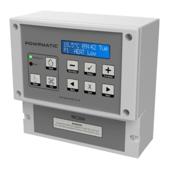
- Page 4 - Press to decrease values. maximum allowed period, and then revert to 0 minutes. Decrease Release the button when the required heating period is showing. page no. 4 of 28 MC200/V3 Users, Installation & Servicing Instructions Doc Ref M401 issue 5.8 January 2022.
- Page 5 Fan button. • Pressing of the next button will scroll through the C 09:42 screen displays available to the user HEAT ON page no. 5 of 28 MC200/V3 Users, Installation & Servicing Instructions Doc Ref M401 issue 5.8 January 2022.
- Page 6 Sets the current date and the time of day. The correct date allows the MC200 to know the day of the week, The second line of the display shows which keypad allows for automatic BST-GMT changeovers, carries ◄...
- Page 7 7 of 28 MC200/V3 Users, Installation & Servicing Instructions Doc Ref M401 issue 5.8 January 2022.
- Page 8 SetPassw **** For Hi/Lo heaters, there are two heater power entries and the MC200 will calculate the run cost according to the level of heat requested. The user may enter a 4-digit password here. Once set,...
- Page 9 Heat On, and the heating will turn appliance. In addition a forward service date can be off only when all timers have reached Heat Off. The page no. 9 of 28 MC200/V3 Users, Installation & Servicing Instructions Doc Ref M401 issue 5.8 January 2022.
- Page 10 • The MC200/V3 keeps a note of how many minutes are output will be 10v. taken for the temperature to drop the number of degrees entered against this parameter when the heating period Cost logging operates as usual.
- Page 11 Protection Rating IP20 Software versions G.12 Dimensions 165mm 85mm C 09:42 Tue HEAT LOW Heat Increase Select Decrease Reset Next Back Quit page no. 11 of 28 MC200/V3 Users, Installation & Servicing Instructions Doc Ref M401 issue 5.8 January 2022.
- Page 12 2.1.2 Location the MC200/V3. Siting of the MC200/V3 is important in that it must be Remove the four screws that secure the top (keypad and fitted where the temperature will be representative of the display) section.
- Page 13 ³ Volt Free - If a voltage is required (230V, 24V, 110V etc) the appropriate voltage must be applied to the corresponding input terminal. page no. 13 of 28 MC200/V3 Users, Installation & Servicing Instructions Doc Ref M401 issue 5.8 January 2022.
- Page 14 2.2 Electrical Cable Installation 2.2.2 External Wiring 2.2.2.1 Wiring details for current Powrmatic heaters utilising fused live output terminal 14 and detailing 'link' wires. 2.2.2.2 Wiring details for older Powrmatic heaters utilising volt free heat and fan terminals Notes: 3 Wiring for external remote sensor only (internal sensor as std)
- Page 15 230V Live to Heater MC200 V3 Terminals Heater Terminals 230V Live to Heater MC200 V3 Terminals Heater Terminals page no. 15 of 28 MC200/V3 Users, Installation & Servicing Instructions Doc Ref M401 issue 5.8 January 2022. 9 10 11 E...
- Page 16 Links MC200 V3 Terminals Heater Terminals 2.3 Interconnecting Wiring Diagrams 10 11 E Link MC200 Controlling 1Pha ErP 2018 CPx Cabinet Heaters with High/Low Control 230V Live to Heater MC200 V3 Terminals Heater Terminals 230V Live to Heater 13 14 15...
- Page 17 Mains Input Mains Input Mains Input Mains Input For SrP HB Radiant Heaters - refer to Supplement ref M314 page no. 17 of 28 MC200/V3 Users, Installation & Servicing Instructions Doc Ref M401 issue 5.8 January 2022.
- Page 18 Links 9 10 11 E Links 230V Live to Heater MC200 V3 Terminals Heater Terminals MC200 Controlling ErP 2018 LNVx or VPx Heaters with optional Modulating Control 230V Live to Heater MC200 V3 Terminals Heater Terminals 10 11 E Link...
- Page 19 230V Live to Heater 230V Live to Heater 230V Live to Heater MC200 V3 Terminals Heater Terminals MC200 V3 Terminals Heater Terminals page no. 19 of 28 MC200/V3 Users, Installation & Servicing Instructions Doc Ref M401 issue 5.8 January 2022.
- Page 20 9 10 Links MC200 V3 Terminals Heater Terminals 230V Live 13 14 to Heater Links MC200 Controlling CPx Cabinet Heaters with optional High/Low Control 230V Live to Heater MC200 V3 Terminals Heater Terminals MC200 V3 Terminals Heater Terminals 13 14...
- Page 21 Heater MC200 V3 Terminals Heater Terminals MC200 V3 Terminals Heater Terminals Links Links 230V Live to Heater 230V Live to Heater page no. 21 of 28 MC200/V3 Users, Installation & Servicing Instructions Doc Ref M401 issue 5.8 January 2022.
- Page 22 Range of adjustment: 0.5°C to 10.0°C the Engineer code permits access to both the Engineer menu and the User menu. your setting here page no. 22 of 28 MC200/V3 Users, Installation & Servicing Instructions Doc Ref M401 issue 5.8 January 2022.
- Page 23 NC = BMS BMS contact open turns heating on NO = BMS BMS contact closed turns heating on your setting here page no. 23 of 28 MC200/V3 Users, Installation & Servicing Instructions Doc Ref M401 issue 5.8 January 2022.
- Page 24 When the heat relay(s) are energised, power will be your setting here applied to the burner(s). The fan relay* (Terminals Fan In page no. 24 of 28 MC200/V3 Users, Installation & Servicing Instructions Doc Ref M401 issue 5.8 January 2022.
- Page 25 • The display will show “Heater lockout”. Both LED’s will initially flash, changing over to just the Fault LED flashing. page no. 25 of 28 MC200/V3 Users, Installation & Servicing Instructions Doc Ref M401 issue 5.8 January 2022.
- Page 26 When this date is reached the MC200 fault indicator will C 09:42 be illuminated and the display will alternate between the normal display and "Service due, call engineer".
- Page 27 3.2 Spare Parts & Options Item Description Part No. Internal Sensor Bead 143070034 Warm Air Sensor 143070031 Black Bulb Sensor 143070032 Duct Sensor 143070035 page no. 27 of 28 MC200/V3 Users, Installation & Servicing Instructions Doc Ref M401 issue 5.8 January 2022.
- Page 28 Energy Association Powrmatic pursues a policy of continues improvement in both design and performance of its products and therefore reserves the right to change, amend or vary specifications without notice. Whilst the details contained herein are believed to be correct they do not form the basis of any contract and interested parties should contact the Company to confirm whether any material alterations have been made since publication of this brochure.
Need help?
Do you have a question about the MC200 and is the answer not in the manual?
Questions and answers