Table of Contents
Advertisement
Quick Links
Operator's Manual
MAXSA
Register your machine:
www.lincolnelectric.com/register
Authorized Service and Distributor Locator:
www.lincolnelectric.com/locator
Save for future reference
Date Purchased
Code:
(ex: 10859)
Serial:
(ex: U1060512345)
IM10024-A
| Issue D ate 13-Mar
© Lincoln Global, Inc. All Rights Reserved.
22 & 29 WIRE DRIVE
™
For use with machines having Code Numbers:
11615, 11616, 11815, 11816
Advertisement
Table of Contents

Subscribe to Our Youtube Channel
Related Manuals for Lincoln Electric MAXSA 22


Summary of Contents for Lincoln Electric MAXSA 22
- Page 1 Operator’s Manual MAXSA 22 & 29 WIRE DRIVE ™ For use with machines having Code Numbers: 11615, 11616, 11815, 11816 Register your machine: www.lincolnelectric.com/register Authorized Service and Distributor Locator: www.lincolnelectric.com/locator Save for future reference Date Purchased Code: (ex: 10859) Serial: (ex: U1060512345) IM10024-A | Issue D ate 13-Mar...
- Page 2 THANK YOU FOR SELECTING A QUALITY PRODUCT BY KEEP YOUR HEAD OUT OF THE FUMES. DON’T get too close to the arc. LINCOLN ELEC TRIC. Use corrective lenses if necessary to stay a reasonable distance away from the arc. READ and obey the Safety Data PLEASE EXAMINE CARTON AND EQUIPMENT FOR Sheet (SDS) and the warning label DAMAGE IMMEDIATELY...
- Page 3 W117.2-1974. A Free copy of “Arc Welding Safety” booklet E205 is available from the Lincoln Electric Company, 2.d. All welders should use the following procedures in order to 22801 St. Clair Avenue, Cleveland, Ohio 44117-1199.
- Page 4 SAFETY ELECTRIC SHOCK ARC RAYS CAN BURN. CAN KILL. 3.a. The electrode and work (or ground) circuits are 4.a. Use a shield with the proper filter and cover plates to protect your electrically “hot” when the welder is on. Do eyes from sparks and the rays of the arc when welding or not touch these “hot”...
- Page 5 SAFETY WELDING AND CUTTING CYLINDER MAY EXPLODE IF SPARKS CAN CAUSE DAMAGED. FIRE OR EXPLOSION. 7.a. Use only compressed gas cylinders containing the correct shielding gas for the process used 6.a. Remove fire hazards from the welding area. If and properly operating regulators designed for this is not possible, cover them to prevent the welding sparks the gas and pressure used.
-
Page 6: Table Of Contents
TABLE OF CONTENTS Page Installation ......................Section A Product Description ........................A-1 Recommended Processes ......................A-1 Process Limitations ........................A-1 Equipment Limitations .........................A-1 Common Equipment ........................A-1 General Information ........................A-2 Design Features ........................A-2 Location of Components ......................A-2 Specifications ..........................A-3 Safety Precautions........................A-4 Non-Safety Standard Equipment..................A-4 Input and Ground Connections ....................A-4 Location and Mounting ......................A-4 High Frequency Protection ....................A-4... -
Page 7: Product Description
PRODUCT DESCRIPTION PRODUCT SUMMARY The MAXsa™ series of Automatic Wire Drives are designed for hard automation, submerged arc weld- ing. The heavy-duty gearbox and feed plate have many years of proven reliability while a new perma- nent magnet motor has been added. The MAXsa™... -
Page 8: General Information
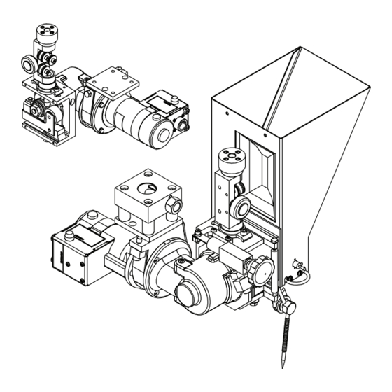
GENERAL INFORMATION DESIGN FEATURES - MAXsa™ 22 • Closed-loop speed control. • Knurled drive rolls. • Heavy cast aluminum gearbox housing and feed plate assembly. • Wire straightener. • Cross Seam Adjuster • Flux Hopper (not shown) • Mounting Hardware for accessories •... - Page 9 INSTALLATION DESIGN FEATURES - MAXsa™ 29 • Closed-loop speed control. • Knurled drive rolls. • Heavy cast aluminum gearbox housing and feed plate assembly. • Wire straightener. • 32Vdc permanent magnet, high torque motor. • Gears included to change speed range. FIGURE A.2 - LOCATION OF MAXsa™...
- Page 10 INSTALLATION DESIGN FEATURES - MAXsa™ 22 • Closed-loop speed control. • Knurled drive rolls. • Heavy cast aluminum gearbox housing and feed plate assembly. • Wire straightener. • Cross Seam Adjuster • Flux Hopper (not shown) • Mounting Hardware for accessories •...
- Page 11 INSTALLATION DESIGN FEATURES - MAXsa™ 29 • Closed-loop speed control. • Knurled drive rolls. • Heavy cast aluminum gearbox housing and feed plate assembly. • Wire straightener. • 32Vdc permanent magnet, high torque motor. • Gears included to change speed range. FIGURE A.2a - LOCATION OF MAXsa™...
-
Page 12: Specifications
SPECIFICATIONS TECHNICAL SPECIFICATIONS - MAXsa™ 22 & 29 WIRE DRIVES Spec. Type 142:1 Speed Ratio 95:1 Speed Ratio 57:1 Speed Ratio Wire Size Wire Size Wire Size Speed Solid Cored Speed Solid Cored Speed Solid Cored K2370-2 MAXsa™ 22 10-200 7/32 5/32 10-300... -
Page 13: Safety Precautions
INSTALLATION SAFETY PRECAUTIONS Read this entire installation section before you start installation. WARNING ELECTRIC SHOCK can kill. • Only qualified personnel should per- form this installation. • Turn the input power OFF at the dis- connect switch or fuse box before working on this equipment. -
Page 14: Power Wave
INSTALLATION POWER WAVE AC/DC 1000 SD SUBARC Mounting Dimensions ® SYSTEM CONNECTIONS ( See Figure A.3) The MAXsa™ Wire Drive can be mounted by using the four 3/8-16 tapped holes or the two 0.562 through Diagram shown is for a single arc system. Refer to the holes. -
Page 15: Changing Wire Drive Configuration
INSTALLATION CHANGING THE WIRE DRIVE 5. Carefully disconnect the Motor leads from the har- CONFIGURATION ness by pulling the quick-connect terminals apart. The MAXsa™ 22 & 29 WIRE DRIVES can be recon- 6. Reverse the motor leads and reconnect the quick- figured to fit in any hard automation application. -
Page 16: Wire Feed Mechanism
A-10 A-10 INSTALLATION WIRE FEED MECHANISM 4. Pull the gear from the shaft using the screws as a pulling device. All MAXsa™ Wire Drive units are shipped with 142:1 5. Be certain woodruff key is properly located on the ratio gears. Gears are included to change to either 95:1 shaft. - Page 17 A-11 A-11 INSTALLATION TABLE A.1 - DRIVE ROLL KITS KP1899 DRIVE ROLL KIT INCLUDED WITH KIT Drive Roll Drive Roll Incoming Outgoing Kit Number Wire Sizes & Types Part Number No. required Guide Guide KP1899-1 3/32-7/32” Wires KP1885-1 KP2116-2 KP1963-1 KP1899-2 1/16-3/32”...
- Page 18 A-12 A-12 INSTALLATION K325 - TC-3 TRAVEL CARRIAGE The TC-3 travel carriage is available in two models. Both are “High Capacity” and suitable for multiple arc FIGURE A.5 welding. K325HC-S (Standard - 952:1 ratio) 5” to 70”/min (127mm to 1.88M/mim) 19”...
- Page 19 A-13 A-13 INSTALLATION INSTALLATION NOTE: To install a MAXsa™ 29 Wire Drive order a The TC-3 comes factory assembled to fit an 8” Mounting Bracket (M6769) and the appropri- (203mm) beam. See print G1458 for instructions to ate Head Support (K29 or M8232). use it on 10”...
- Page 20 A-14 A-14 INSTALLATION INCLINED OPERATION OF TC-3 1. The beam should have a Knurled Drive Flange and the TC-3 should have the straight toothed Drive Gear (T13586 - ordered separately). CAUTION When the carriage is used in an inclined application the unit is free to move whenever the Carriage Release Handle is pulled down.
- Page 21 A-15 A-15 INSTALLATION FIGURE A.7 - DRIVE GEAR TRACKING Incorrect ADD Shims Shims Full Face Incorrect Beam Drive Gear .88” Contact REMOVE Shims Drive Rail DRIVE GEAR TRACKING FIGURE A.8 - BEARING TRACKING The TC-3 is shimmed at the factory so that the drive gear sits flat against a .88”...
-
Page 22: Operation
OPERATION ROUTINE OPERATION 2. On-the-fly Starting - refers to starting the weld Once the procedures and parameters are properly set after the travel begins to get a “scratch” start. at the controller the operator should be able to make Normally this type of starting requires the use of a production welds without changing those settings. - Page 23 FIGURE B.2 - HORIZONTAL ADJUSTMENT This Adjustment Can be Locked by Tightening Two Socket Head Screws Turn Handle to adjust MAXsa 29 MAXsa 22 Rotating the K96 Allows for 2” Movement in any Direction in the Horizontal Plane 2” 2 1/2”...
-
Page 24: Options And Accessories Website
ACCESSORIES OPTIONS AND ACCESSORIES available at www.lincolnelectric.com Follow these steps: 1. Go to www.lincolnelectric.com 2. In the Search field type E9.181 and click on the Search icon (or hit ‘Enter’ on the keyboard). 3. On the Results page, scroll down to the Equipment list and click on E9.181. - Page 25 ACCESSORIES SUBMERGED ARC CONTACT Connect the lug on the electrode cables from the power source to the tab on the contact nozzle ASSEMBLIES and tighten the bolt and nut. See Figure C.1. K231-[X/XX] CONTACT NOZZLE Operation - DO NOT completely straighten the The K231- [x/xx] is used for submerged arc weld- electrode.
- Page 26 ACCESSORIES K226 CONTACT ASSEMBLY Maintenance - Rusty or dirty wire and/or exces- The K226 assemblies are used for welding at currents sively high welding currents increase wear on the from 600 to 1000 amps. contact jaws. When arcing occurs or the electrode becomes loose in the jaws, remove the jaws and Model K226-T - (2 tapered jaws) ‘dress’...
- Page 27 ACCESSORIES 7. Slide the center guide (G) up out of the pivot body K148 CONTACT NOZZLE AND K149 Linc-Fill until the tang is above the window. LONG STICKOUT EXTENSION 8. Place the Linc-Fill guide assembly into the nozzle This nozzle is available in three models and can be window, and then lower the center guide tube (G) used for Innershield or submerged arc processes.
- Page 28 ACCESSORIES Operation 10. Line up the lower spot in the center guide tube (G) with the 3/8” (9.5 mm) set screw (H) and tighten the screw securely. The same contact tip, S13763, is used for 3/32” (2.4 mm) through 3/16” (4.8 mm) diameter electrodes. 11.
- Page 29 ACCESSORIES K285 Installation to the K148 To install a new contact tip proceed as follows: 1. Clip the end of the electrode and inch it up until it is 1. Remove the tension on the center guide tube using free of the tip. a “C”...
- Page 30 ACCESSORIES K285 Installation with K149 K285 installation with the K129 1. Install the K149 to the K148 per the instructions. 1. Unscrew the hose clamps enough so they can slip over the tip holder clamping nut. 2. Loosen the hose clamps of the K285 entirely, place them around the nozzle and tighten them so that 2.
- Page 31 ACCESSORIES K285 Used in Horizontal Fillet Applications 1. With K148 or K148/K149 combination - After the c. Loosen the K285 hose clamps and rotate the flux cone unit about 40 to 45° and retighten the K285 has been attached to the nozzle body: clamps.
-
Page 32: Vertical Head Adjuster
ACCESSORIES K29 VERTICAL HEAD ADJUSTER 4. Slide the Head Adjustment Lock (A) over the end Automatic welding applications frequently require rais- of the Mounting Bracket (M). ing and/or lowering of the feed head assembly. The K29 provides an easy method of accomplishing this 5. -
Page 33: Horizontal Head Adjuster
C-10 C-10 ACCESSORIES K96 HORIZONTAL HEAD ADJUSTER FIGURE C.14 - K96 The K96 provides an easy means of moving the Feed Head in a horizontal direction by simply turning a crank handle. It provides 2” (51mm) of travel and can be mounted directly to the Head Support or to a K29 Vertical Lift Adjuster. -
Page 34: K129 Tiny Twinarc Kit
C-11 C-11 ACCESSORIES FIGURE C.16 - K129 TINY TWINARC COMPONENTS ® 1 - Nozzle Assembly A - Drive Rolls 2 - Guide Tubes B - Guide Tubes 3 - Locking Collar C - Idle Roll Arm 4 - Contact Tip(s) D - Incoming Wire Guide 5 - Tip Holder E - Drive Roll Spacer... - Page 35 C-12 C-12 ACCESSORIES B. For 3/32 (2.4mm) Wire 1. Remove the items listed in Step “A” plus: 5. Insert the two long insulated wire guides (2) into the Twinarc nozzle (1) making sure that they are • The drive roll key. seated in the holes in the mounting block (7).
- Page 36 C-13 C-13 ACCESSORIES FIGURE C.18 - K225 TWINARC COMPONENTS ® A - Drive Rolls B - Guide Tubes C - Idle Roll Arm D - Drive Roll Spacer E - Key F - Nozzle Assembly K225 SUBMERGED ARC TWINARC ® NOTE: The idle roll arm pivot pin is held in place by a set screw that is accessed from the outgoing Twin arc welding is a process where two wires of the...
- Page 37 C-14 C-14 ACCESSORIES Nozzle Installation (See Figure C.18) IMPORTANT Make sure that the mating surface (8) between the 1. install the new idle roll arm (C) using the pin and Center Block (4) and the Copper Bar (2). is bright, set screw from the original assembly.
-
Page 38: K281 Solid Wire Straightener For Twinarc
C-15 C-15 ACCESSORIES K281 SOLID WIRE STRAIGHTENER FOR 4. Insert one wire through each of the guide block holes. TINY TWINARC ® 5. Push both wires through and between the rollers The K281 wire straightener can be used to straighten and down through the guide tube until they touch .045”... -
Page 39: Maintenance
MAINTENANCE SAFETY PRECAUTIONS SENSE LEAD FUSE There should never be any current flowing through WARNING the sense leads! The sensing lead circuit is current protected in the Power Wave AC/DC 1000 SD. ® If the MAXsa™ 22 & 29 Wire Drives are used in an ELECTRIC SHOCK can kill. -
Page 40: Troubleshooting
HOW TO USE TROUBLESHOOTING GUIDE WARNING Service and Repair should only be performed by Lincoln Electric Factory Trained Personnel. Unauthorized repairs performed on this equipment may result in danger to the technician and machine operator and will invalidate your factory warranty. For your safety and to avoid Electrical Shock, please observe all safety notes and precautions detailed throughout this manual. - Page 41 TROUBLESHOOTING Observe all Safety Guidelines detailed throughout this manual PROBLEMS POSSIBLE AREAS OF RECOMMENDED (SYMPTOMS) MISADJUSTMENT(S) COURSE OF ACTION OUTPUT PROBLEMS Drive rolls turn, but wire will not 1. Wire jammed or kinked on route feed or wire feeding is rough or through wire drive.
- Page 42 DIAGRAMS MAXsa™ 22 & 29 WIRE DRIVES...
- Page 43 DIMENSION PRINT MAXsa™ 22 & 29 WIRE DRIVES...
- Page 44 DIMENSION PRINT MAXsa™ 22 & 29 WIRE DRIVES...
- Page 45 DIMENSION PRINT MAXsa™ 22 & 29 WIRE DRIVES...
- Page 46 NOTES MAXsa™ 22 & 29 WIRE DRIVES...
- Page 47 Do not touch electrically live parts or Keep flammable materials away. Wear eye, ear and body protection. WARNING electrode with skin or wet clothing. Insulate yourself from work and ground. Spanish No toque las partes o los electrodos Mantenga el material combustible Protéjase los ojos, los oídos y el AVISO DE bajo carga con la piel o ropa moja-...
- Page 48 Keep your head out of fumes. Turn power off before servicing. Do not operate with panel open or WARNING Use ventilation or exhaust to guards off. remove fumes from breathing zone. Spanish Los humos fuera de la zona de res- Desconectar el cable de ali- No operar con panel abierto o AVISO DE...
- Page 49 • World's Leader in Welding and Cutting Products • • Sales and Service through Subsidiaries and Distributors Worldwide • Cleveland, Ohio 44117-1199 U.S.A. TEL: 216.481.8100 FAX: 216.486.1751 WEB SITE: www.lincolnelectric.com...
Need help?
Do you have a question about the MAXSA 22 and is the answer not in the manual?
Questions and answers