Table of Contents
Advertisement
Quick Links
Advertisement
Table of Contents

Related Manuals for PCB Piezotronics F8159-0112A


Summary of Contents for PCB Piezotronics F8159-0112A
- Page 1 Model F8159-0112A STRAIN GAGE SENSOR SIGNAL CONDITIONER Installation and Operating Manual For assistance with the operation of this product, contact the PCB Piezotronics, Inc. Toll-free: 716-684-0001 24-hour SensorLine: 716-684-0001 Fax: 716-684-0987 E-mail: info@pcb.com Web: www.pcb.com...
- Page 2 Assistance is needed to safely operate equipment PCB Piezotronics is an ISO-9001 certified company whose Damage is visible or suspected calibration services are accredited by A2LA to ISO/IEC Equipment fails or malfunctions 17025, with full traceability to SI through N.I.S.T.
- Page 3 CAUTION Refers to hazards that could damage the instrument. NOTE Indicates tips, recommendations and important information. The notes simplify processes and contain additional information on particular operating steps. The following symbols may be found on the equipment described in this manual: This symbol on the unit indicates that high voltage may be present.
- Page 4 PCB工业监视和测量设备 - 中国RoHS2公布表 PCB Industrial Monitoring and Measuring Equipment - China RoHS 2 Disclosure Table 有害物质 镉 汞 铅 (Pb) 六价铬 (Cr(VI)) 多溴联苯 (PBB) 多溴二苯醚 (PBDE) 部件名称 (Hg) (Cd) 住房 PCB板 电气连接器 压电晶体 环氧 铁氟龙 电子 厚膜基板 电线 电缆 塑料 焊接...
- Page 5 Component Name Hazardous Substances Lead (Pb) Mercury (Hg) Cadmium (Cd) Chromium VI Polybrominated Polybrominated Compounds Biphenyls (PBB) Diphenyl Ethers (Cr(VI)) (PBDE) Housing PCB Board Electrical Connectors Piezoelectric Crystals Epoxy Teflon Electronics Thick Film Substrate Wires Cables Plastic Solder Copper Alloy/Brass This table is prepared in accordance with the provisions of SJ/T 11364.
-
Page 6: Table Of Contents
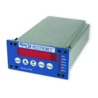
SERIES 8159 SIGNAL CONDITIONER MANUAL TABLE OF CONTENTS Section Page DESCRIPTION INSTALLATION WIRING SWITCH DEFINITION FUNCTION DEFINITIONS OPERATING INSTRUCTIONS CALIBRATION INSTRUCTIONS OPTIONS Figure Page Series 8159 Front Panel View Series 8159 Rear Panel View Panel Mounting Cut-Out Dimensions Transducer Wiring Input/Output (I/O) Wiring Location of Jumpers and Potentiometers (Top View) SW1 Switch Settings... -
Page 7: Description
SERIES 8159 SIGNAL CONDITIONER MANUAL DESCRIPTION The Series 8159 is a microprocessor-based digital indicator capable of interfacing directly to low level strain gage transducers. An internal, high gain, fully differential amplifier and a 4-½ digit analog-to-digital converter combine to accurately digitize the input signal. A 5V @ 60mA or 10V @ 120mA, short circuit protected, transducer excitation supply is also provided. -
Page 8: Installation
SERIES 8159 SIGNAL CONDITIONER MANUAL Figure 2 - Series 8159 Rear Panel View INSTALLATION The Series 8159 enclosure is designated for panel mounting in a 1/8 DIN cutout. The cutout dimensions are shown below. Figure 3 - Panel Mounting Cutout Dimensions To panel mount the 8159, perform the following steps: 1. -
Page 9: Wiring
SERIES 8159 SIGNAL CONDITIONER MANUAL WIRING Reference Figures 4 and 5 for TRANSDUCER and INPUT/OUTPUT (I/O) wiring information. Power is applied with a 3-prong AC power cord. The instrument is protected by a 250V, 250mA fast acting 5mm fuse. The fuse holder is an integral part of the input power connector. A spare fuse is provided in the fuse holder. - Page 10 SERIES 8159 SIGNAL CONDITIONER MANUAL Figure 5 - Input/Output (I/O) Wiring...
- Page 11 SERIES 8159 SIGNAL CONDITIONER MANUAL Figure 6 - Location of Jumpers and Potentiometers (Top View) Warning: Remove AC power to the 8159 Meter before removing any enclosure panels or making any internal adjustments or changes. Switch 1 Switch 2 Switch 3 Switch Switch Bridge...
- Page 12 SERIES 8159 SIGNAL CONDITIONER MANUAL Warning: Remove AC power to the 8159 meter before removing any enclosure panels or making any internal adjustments or changes. Housing RCAL Resistor Rear Panel Figure 9 - Location of RCAL Resistor (Top View) Warning: Remove AC power to the 8159 meter before removing any enclosure panels or making any internal adjustments or changes.
-
Page 13: Switch Definition
SERIES 8159 SIGNAL CONDITIONER MANUAL SWITCH DEFINITIONS Mode Selection Switch (S1) S1 is used to cycle through the various set points, Hysteresis, and calibration values and decimal point locations. The sequence is as follows. The designators, in parenthesis, identify text that will be displayed, momentarily, followed by the value. -
Page 14: Function Definitions
SERIES 8159 SIGNAL CONDITIONER MANUAL Decrement Switch (S3) This switch serves two functions, depending on the present status of S1. If the instrument is in the Mode Selection sequence, this switch will decrement the flashing digit. If the instrument is in its operating mode, S3 becomes an AUTO CAL switch. CAUTION: Depressing this switch will cause the instrument to recalibrate its full-scale reading. -
Page 15: Operating Instructions
SERIES 8159 SIGNAL CONDITIONER MANUAL Set Point Low 2 (SPL2) SPL2 is independent and functions identically to SPL1. SPL2 has its own relay contact outputs and front panel LED (L2). Hysteresis High (HH) HH is the hysteresis value for SPH1 and SPH2. The hysteresis value determines the number of counts the displayed reading must fall below SPH1 and SPH2 values before deactivating their respective relays and LEDs. - Page 16 SERIES 8159 SIGNAL CONDITIONER MANUAL PROGRAM INSTRUCTIONS Four front panel switches (S1, S2, S3, S4) allow the user to program Set Point, Hysteresis, Calibration Number (CAL) and Decimal Points and monitor minimum, maximum or real time values. 1. Depress MODE (S1) switch once. The text SPH1 followed by the current value of Set Point High 1 (SPH1) will be displayed.
-
Page 17: Calibration Instructions
SERIES 8159 SIGNAL CONDITIONER MANUAL REMOTE TARE (ZERO) Remote zero will tare out any residual value, such as that caused by fixturing a load cell into a test stand. It is activated by momentarily connecting pin 14 to pin 5 on the 15-pin I/O connector REMOTE REBOOT This feature is used to clear the high or low set points if required. - Page 18 SERIES 8159 SIGNAL CONDITIONER MANUAL 8. With no load on the transducer, verify the instrument reading is low. 9. Depress the INCREMENT (S2) switch and hold until the TARE LED illuminates. The readout should be ZERO +/- 1 digit. 10. Apply the FULL SCALE load to the transducer. If a strain gage simulator is used, set it to the desired mV/V setting.
- Page 19 SERIES 8159 SIGNAL CONDITIONER MANUAL 4. Set the CAL NUMBER to the full-scale value provided with the RCAL resistor. This is the shunt calibration valve indicated on the sensor’s calibration certificate. Example: If the RCAL resistor supplied with the instrument creates an output equivalent to 80% of a full-scale 500-pound load, set the CAL NUMBER to 400.00, 0400.0 or 00400.
-
Page 20: Options
SERIES 8159 SIGNAL CONDITIONER MANUAL OPTIONS RS232 SERIAL COMMUNICATION OUTPUT The RS232 transmission is of the displayed reading and is transmitted once every display update, if the DSR line is TRUE (HIGH). The data format is described below. 1. No parity bit 2. -
Page 21: Figure 12
SERIES 8159 SIGNAL CONDITIONER MANUAL Figure 12...
Need help?
Do you have a question about the F8159-0112A and is the answer not in the manual?
Questions and answers