
Related Manuals for Busy Bee tools BBTS10

Summary of Contents for Busy Bee tools BBTS10
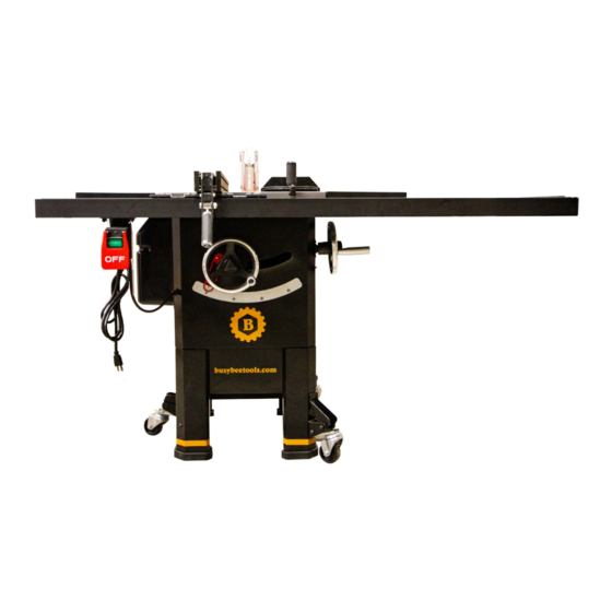
- Page 1 10” 2HP Hybrid Table Saw BBTS10 User’s Manual NO PORTION OF THIS MANUAL MAY COPYRIGHT 2023 BY BUSY BEE TOOLS LTD. BE REPRODUCED WITHOUT THE WRITTEN CONSENT OF BUSY BEE TOOLS LTD. v1.1...
-
Page 2: Warnings
Warnings This manual provides critical safety instructions on the proper setup, operation, maintenance, and service of this machine/tool. Save this document, refer to it often, and use it to instruct other operators. Failure to read, understand and follow the instructions in this manual may result in fire or serious personal injury—including amputation, electrocution, or death. -
Page 3: Table Of Contents
Contents Operations Warnings General Introduction Operation Overview Contact Information Workpiece Inspection Manual Accuracy Non-Through & Through Cuts Machine Specifications Non-Through Cut Shipping Dimensions Through Cut Electrical Blade Size Requirements Motors Blade Selection Main Specifications Ripping Blade Identification Cross Blade Control & Components Combination Blade Safety Laminate Blade... - Page 4 Setup for the 90° Stop Wires and Connections Wire and electrical component damage Setup for the 45° Stop Alterations Miter Slot to Blade Parallelism The Motor Spreader/Riving Knife Alignment Capacitors Adjusting The Spreader Alignment Circuit Requirements Adjusting a Bent Spreader/Riving Knife Difficulties and issues Fence Adjustment Electrical Diagrams...
-
Page 5: Introduction
Our intention is to provide you with this manual to describe the basic information for safety, setup, operation, and maintenance of your new machine. We at Busy Bee Tools are committed and pride ourselves in customer satisfaction. -
Page 6: Main Specifications
Carton #2 Type. Cardboard Box Content ........................... Fence, Rails, and Hardware Weight ............................. 38 lbs. Length x Width x Height ....................... 66 x 16 x 6 in. Ship upright ..........................No Electrical Power Requirement..........................120V or 240V, Single Phase, 60 Hz Prewired Voltage........................... - Page 7 Fence Information Fence Type ............................Camlock T-Shape w/ Aluminum Face Fence Size Length ..........................35-3/4 in. Fence Size Width ..........................3-1/8 in. Fence Size Height ..........................2-7/16 in. Fence Rail Type ............................Extruded Aluminum Fence Rail Length..........................64 in. Fence Rail Width ...........................3-1/8 in. Fence Rail Height ..........................2-1/4 in. Miter Gauge Information Miter Gauge Slot Type ........................T-Slot Miter Gauge Slot Size Width.
-
Page 8: Identification
Identification Control & Components Refer to Figures 1 and the following descriptions to become familiar with the basic controls and components of this machine. Understanding these items and how they work will help you understand the rest of the manual and stay safe when operating this machine. -
Page 9: Safety
SAFETY For your own safety, please read the instruction manual Instructions for Machinery before operating this machine. OWNER’S MANUAL. Read and understand this owner’s manual BEFORE using the machine. The purpose of safety symbols is to attract your attention to possible hazards. -
Page 10: Added Safety Measures For Table Saws
HEARING PROTECTION. Always wear hearing protection MAINTAIN WITH CARE. Follow all maintenance instructions when operating or observing loud machinery. Extended and lubrication schedules to keep machine in good working exposure to this noise without hearing protection can cause condition. A machine that is improperly maintained could permanent hearing loss. -
Page 11: Preventing Kickback
speed before cutting, feed workpiece from front of saw, wood products, laminate covered wood products, and some making sure workpiece is flat against table and a fence, plastics. Never cut materials not intended for this saw. miter gauge, or other guide is used to feed workpiece in a Preventing Kickback straight line. -
Page 12: Protecting Yourself From Kickback
Protecting Yourself from Kickback multiple motors, this is the amperage Even if you know how to avoid kickback, it may still drawn by the largest motor or sum happen. Here are some ways to protect yourself if kickback of all motors and electrical devices DOES occur: that might operate at one time during normal operations. -
Page 13: Grounding Requirements
Grounding Requirements For 240V Connection This machine MUST be grounded. In the event of certain A NEMA 6-15 plug has a grounding prong that must be types of malfunctions or breakdowns, grounding provides attached to the equipment-grounding wire inside the a path of least resistance for electric current to travel—to included power cord. -
Page 14: Setup
If you notice the machine has been damaged Wire Cutters/Stripper ............1 during shipping, please contact your Busy Bee Tools branch immediately. To convert the Model BBTS10 to 240V, do these steps: This machine presents 1 - DICONNECT THE MACHINE FROM POWER! serious injury hazards 2 - Cut off existing NEMA 5-15 plug. -
Page 15: Box 1 &2 Inventory
Box 1 &2 Inventory Box 1 Contents (Figure 6) ............Qty A. Extension Wings ..............2 B. Spreader/Riving Knife ............1 C. Dado Insert ................1 D. Table Inser ................1 E. Saw Blade 10” x 40T ............1 F. Blade Guard Assembly ............1 G. Push Stick ................1 H. -
Page 16: Hardware Identification Chart
Hardware Recognition Chart -16- Model G1023RL Series (Mfd. Since 12/21) -
Page 17: Cleaning The Machine
Initial Cleaning of the Machine Machine Placement To prevent corrosion during shipment and storage of your Weight Load machine, the factory has coated the bare metal surfaces of your machine with a heavy-duty rust prevention compound. Refer to the Machine Specifications section for the weight of your machine. -
Page 18: Lighting
Lighting 3 - Install leg brace (see figure 11) with pre-installed (4) Lighting must be adequate in the area where the machine is M8-1.25X16mm button head cap screws and (4) M6- setup to perform all operations safely. Any shadows, glare, 1X12mm button head carp screws. - Page 19 6 - Turn the blade tilt hand wheel until the tilt indicator is pointing at the 15° angle (see figure 12). 7 - Inspect the joining surfaces of the cast iron table for burrs or foreign material that may inhibit the installation of the extension wings.
- Page 20 12 - Reinstall the endcap and screw it with the tap screw on the fence’s rail (see figure 19). Figure 19: Endcaps reinstalled. Figure 16: Blots for switch box. 13 - Align all the (8) bolts you previously installed on the rail with the holes in the table then insert all the slots into the table making sure that the scale is facing up.
- Page 21 18 - Place the fence on the from rail, as shown in figure21. Press the locking handle down to lock the fence in position. Figure 23: Checking fence calibration. 24 - Perform a check by moving the fence to the 1” mark on the scale and measure the distance between the blade tooth and the fence.
- Page 22 28 - With the aid of an assistant install the fence rail brace with M8-1.25X16mm cap screw and M8-1.25 hex nut (see figure 24). NOTE DO NOT TIGHTEN THE CAP SCREWS YET. Figure 26: Fence back brace Installed. 33 - Secure hex bolt on front of rail brace from Step 30 Figure 24: Attaching rear end brace.
-
Page 23: Dust Collection
35 - Install miter gauge handle and 6 x 20mm flat washer into miter gauge (see Figure 28). Figure 29: Lock-out function and pin. Test Run Once assembly is complete, test run the machine to ensure Figure 28: Miter gauge installed. it is properly connected to power and safety components are functioning properly. -
Page 24: Recommended Adjustments
Operation Overview - If the machine starts, stop the machine immediately. The lock-out pin isn’t working correctly. This safety The objective of this overview is to prepare the beginner feature must function properly before proceeding machine operator with an essential understanding of how with regular operations. -
Page 25: Non-Through & Through Cuts
“how-to” books before starting any projects. Non-Through & Through Cuts Regardless of this section, Busy Bee Tools cannot and will Non-Through Cut not be liable for accidents caused by lack of training or experience. -
Page 26: Blade Selection
Using any blade that • Wobble Dado Blade: A single blade mounted at doesn’t meet the a slight angle on an arbor hub. The blade angle is specifications above will adjustable on the hub, and the width of the dado cut is present a hazardous and controlled by the angle setting of the blade. -
Page 27: Blade Guard Assembly
downward position against the table during idle operation, and the hinge mechanism must be maintained in good working condition so the guard can freely pivot up and down to accommodate the height of the workpiece and return to the table surface. Riving Knife/ Spreader The spreader is a metal plate that prevents the newly cut kerf of the workpiece from pinching the back side of the... -
Page 28: Anti-Kickback Pawls
Anti-Kickback Pawls 5 - Reinstall the table insert. 6 - Push the guard lever toward the front of the saw. 8 The anti-kickback pawls allow the workpiece to travel in 7 - Insert the rear pin on the guard into the rear slot of only one direction. -
Page 29: Spreader/Riving Knife
way through the thickness of the workpiece). Like the spreader, the riving knife acts as a barrier to keep the workpiece from pinching the blade causing kickback. When using as a riving knife, the spreader/riving knife must be kept within the range shown in Figure 42. For that reason, a 10”... -
Page 30: Ripping
When to Use the Riving Knife: respiratory protection before starting the cut. Use the riving knife for all non-through cuts made with a 8 - Re-connect the saw to the power line or remove the standard table saw blade (i.e., dadoes or rabbet cuts, etc.), lock-out pin and turn the saw ON. -
Page 31: Dado Cutting
A dado blade with a diameter up to 10” can be used with the BBTS10 table saw. The riving knife must be installed when using the dado blade to prevent injury from a kickback. DO NOT use the dado blade to perform through cut, it is very risky, and it’ll cause serious injury to the operator. -
Page 32: Rabbet Cuts
what type of cut it’ll be i.e., rip cut or crosscut. We need 7 - Next lay the workpiece on the table and perform the to set up the saw accordingly see pages 42- 43 for second cut after readjusting the fence. more information. -
Page 33: Safety Accessories
3 - Install a ripping blade, and the riving knife, then 7 - Now raise the blade to 1” or half the height of the lower the blade below the table’s height and install the workpiece (whichever is less). zero-clearance table insert. 8 - Re-connect the saw and turn it on, feed the workpiece through the machine in multiple passes 4 - Attach the auxiliary fence to the standard fence and... -
Page 34: Maintenance
Cleaning & Protection Maintenance The cleaning process is easy if it is done periodically by following the above plan. Always vacuum any wood chips General and saw dust from the machine and the surrounding area. This machine like any other machine, needs scheduled Wipe off all remaining dust with a dry cloth. -
Page 35: Blade Tilt Adjustment
Always unplug the machine 4 - Unscrew the motor cover and remove it. during service and 5 - Loosen the (2 M8-1.25 )nuts on the leadscrew maintenance. Electrocution, please refer to figure 44. and serious injuries will o ccur if this warning is ignored. 6 - You need to tilt the blade slightly until you have enough room to adjust the nuts. - Page 36 Miter Slot to Blade Parallelism The best results can be obtained from this table saw only when it is setup correctly, and when the miter slot, the fence and the blade are all parallel. This is a step that must be done by the machine owner due to the fact that this machine isn’t fully assembled it’ll need a Little of your care and attention.
- Page 37 Tools Needed: 9 - Loosen the (4) table mounting bolts the same way as in step 6. A 12” min. straightedge ..........1 10 - Refer to figures 42, and 43 for shim positioning. If the distance between position A and the blade Please follow these steps to check and align the riving is shorter that position B the shims must be placed knife with the blade:...
- Page 38 Adjusting The Spreader Alignment Fence Adjustment The mounting bracket for the spreader/riving knife has (2) cap screws for adjustment, they are located on the (L) shaped riving knife bracket. In principle a fence has three parameters: first, is it square to the table. Second, is the gap between the Tools Needed fence &...
-
Page 39: Fence Size Height
Fence Handle clamping Pressure adjustment 1 - Remove the fence and lay it upside down. 2 - Loosen the knurled nut see figure 50. Figure 58: Fence height gap. 3 - Loosen the knurled lock nuts and adjust the set screw on the face of the fence bracket see figure 57 Until the angle is perfectly 90°... - Page 40 1- DISCONNECT THE MACHINE FROM THE POWER Fence Scale Calibration SOURCE. The fence has two indicators one on the left the other on 2 - Slide the fence and place it against the edge of the right. These indicators can be calibrated by loosening the mounting screws and sliding them so that the viewer is miter gauge slot.
-
Page 41: Table
Tools you’ll Need: Philips head screw #2 ..........1 Straight edge ..............1 Follow these steps to adjust the insert: 1 - Disconnect the table saw from power source. 2 - Lower the blade completely. 3 - Place the straight edge across the insert and the table. - Page 42 Figure 67: belt tensioning hex bolt. Tensioning The Belt Follow these steps: 1 - DISCONNECT THE TABLE SAW FROM THE POWER SUPPLY. 2 - Remove the motor cover (located on the side of the machine). 3 - Set the blade tilt at 0° on the scale and raise the blade to the 2”...
- Page 43 Troubleshooting Problem Possible Cause Solution 1. Install the disabling key in the Machine doesn’t start / trips the 1. Switch disabling key not installed. breaker 2. Panel breaker is tripped. ON/OFF switch. 3. Power supply OFF or at fault. Replace the breaker of 4.
-
Page 44: Trunnions
Problem Possible Cause Solution Material is moving away from the Fence is misaligned Check and adjust the rip fence. fence when ripping The blade isn’t aligned with the miter 1. Blade is damaged. 1. Replace damaged blade. slot or the fence 2. - Page 45 Problem Possible Cause Solution Too much sawdust is blowing back 1. The blade guard is removed. 1. Re-install the blade guard. 2. Lack of dust collection due to air 2. Seal the leaks in the cabinet. leaking into the cabinet. 3.
- Page 46 Difficulties and issues Electrical In the event when you are experiencing any difficulties or issues understanding any part of this manual, please Electrical Safety STOP what you are doing and contact our customer service and technical support department at the phone number Shock Hazard mentioned at the start of this manual.
- Page 47 Figure 70: Start/Stop switch box. Figure 72: Electric Diagram. Stop, READ, AND UNDERSTAND THE ELECTRICAL SEAFETY SECTION ON PAGE 12 through 15. Figure 71: Run and star capacitors.
- Page 48 Parts and Diagrams Main Figure 73: Main table & elevation mechanism Figure 74: table diagram.
- Page 49 Figure 75: Trunnion and motor diagram. Main Parts List Ref. Number Part Number Description Quantity PBBTS1024 Screw M8X30 PBBTS1027 Lock Nut M16 PBBTS1028 Flat washer PBBTS10MOT Motor PBBTS1029-1 29-1 Motor Fan Cover PBBTS1029-2 29-2 Motor Fan PBBTS1029-3 29-3 Motor Electric Box PBBTS1029-4 29-4 Run Cap.
- Page 50 Ref. Number Part Number Description Quantity PBBTS1031 Socket Head Three Combination Screw M6-1.0×25mm PBBTS1034 Socket Set Screw M5-0.8×8mm PBBTS1035 Motor Pulley PBBTS1036 PBBTS1037 Drive Belt PBBTS1038 Blade Bracket PBBTS1039 Bushing PBBTS1040 Arbor Pulley PBBTS1041 Lock Nut M12-1.75 PBBTS1042 Shim Washer PBBTS1043 Pan Head Screw M4-0.7×6 PBBTS1044...
- Page 51 Ref. Number Part Number Description Quantity PBBTS1075 Blade PBBTS1076 Arbor PBBTS1077 PBBTS1078 Bearing 6203-ZZ PBBTS1079 Bearing 6202-ZZ PBBTS1080 Retaining C-RING PBBTS1081 Socket Set Screw M5×6 PBBTS1082 Mounting Plate PBBTS1083 Bushing PBBTS1084 Shaft Pin PBBTS1085 Lock Bolt PBBTS1086 Riving Lock Level PBBTS1087 Clamp PBBTS1088...
- Page 52 Ref. Number Part Number Description Quantity PBBTS10122 Socket Head Three Combination Screw M5-0.8×10mm PBBTS10123 Socket Head Screw M5-0.8×10mm PBBTS10124 Dado Insert PBBTS10125 Hex Wrench 2.5mm PBBTS10126 Socket Head Three Combination Screw M5-0.8×16mm PBBTS10127 Worm Wheel Plate...
- Page 53 Cabinet Assembly Figure 76: Cabinet assembly. Figure 77: Stand Assembly.
- Page 54 Cabinet Assembly Parts Reference # Part Number Description Quantity PBBTS10201 Upper Frame Assembly PBBTS10202 Front Panel Assembly PBBTS10203 Rear Panel Assembly PBBTS10204 Left Side Cover PBBTS10205 Right Side Cover PBBTS10206 Rear Cover PBBTS10207 Motor Cover PBBTS10208 Socket Head Three Combination Screw M6-1.0 X 16mm PBBTS10209 Socket Head Screw M5-0.8×10mm PBBTS10210...
-
Page 55: Rails
Fence and Rails Figure 78: Fence and rails assembly. Fence and Rails Parts List Reference # Part Number Description Quantity PBBTS10301 Rear Rail PBBTS10302 Rear Rail Cap PBBTS10303 Bolt M8-1.25X25mm PBBTS10304 Hex Nut M8-1.25 PBBTS10305 Fence Plate PBBTS10306 Socket Head Screw M8-1.25×16mm PBBTS10307 Tapping Screw ST4.2×13 PBBTS10308... - Page 56 Reference # Part Number Description Quantity PBBTS10320 Eccentric Wheel PBBTS10321 Screw M8×8 PBBTS10322 Compression Spring PBBTS10323 Steel Ball PBBTS10324 Scale PBBTS10325 Tapping Screw ST3.5×9.5 PBBTS10326 Hex Head Bolt M8-1.25×25mm PBBTS10327 Front Rail End Cover (Right) PBBTS10328 Front Rail PBBTS10329 Front Rail End Cover (Left) PBBTS10330 Pointer Plate PBBTS10331...
- Page 57 Blade Guard Figure 79: Blade guard assembly. Blade Guard Parts List Reference # Part Number Description Quantity PBBTS10401 Lock Nut M5-0.8 PBBTS10402 Set Pin PBBTS10403 Spring PBBTS10404 PBBTS10405 Top Barrier PBBTS10406 Barrier PBBTS10407 Connection Rod PBBTS10408 Stepped Screw M5 PBBTS10409 Stepped Screw M6 PBBTS10410 Pan Head Screw M5-0.8×10mm...
- Page 58 Reference # Part Number Description Quantity PBBTS10417 Right Anti-Kickback Pawls PBBTS10418 Riving Knife PBBTS10419 Spring PBBTS10420 Steel ball PBBTS10421 Flat washer PBBTS10422 Tapping Screw ST2.9x6 PBBTS10423 Socket Head Screw M5-0.8x27mm PBBTS10424 Protection Cover PBBTS10425 Washer Mitre Guage Figure 80: Miter gauge assembly.
- Page 59 Mitre Guage Parts List Reference # Part Number Description Quantity PBBTS10501 Angle Indicator PBBTS10502 Upper Handle Cap PBBTS10503 Lower Handle Cap PBBTS10504 Cap Screw M8-1.25×55mm PBBTS10505 Washer PBBTS10506 Miter Handle PBBTS10507 Miter Pin PBBTS10508 Miter Bar Guide Washer PBBTS10509 Miter Gauge Body PBBTS10510 Miter Bar PBBTS10511...
- Page 60 This warranty shall not apply to consumable products such as blades, bits, belts, cutters, chisels, punches etc. Busy Bee Tools shall in no event be liable for injuries, accidental or otherwise, death to persons or damage to property or for incidental contingent, special or consequential damages arising from the use of our products.
Need help?
Do you have a question about the BBTS10 and is the answer not in the manual?
Questions and answers