Advertisement
Quick Links
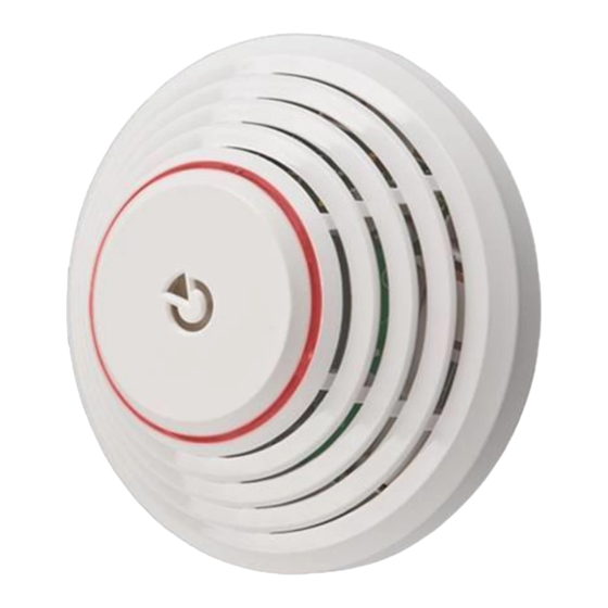
The JA-151ST Wireless combined smoke and heat detector
The JA-151ST is a component of the JABLOTRON JA-100
alarm system. It is used to detect fire hazards in the interior of
residential or commercial buildings. The detector can be installed in
mobile homes or caravans. The product is not designed to be
installed in industrial premises. The JA-151ST detector uses
wireless communication and it is powered with three AA batteries.
The detector should be installed by a trained technician with a valid
with a valid manufacturer's certificate.
The detector indicates a fire hazard using the built-in LED
indicator and acoustic signalling.
The JA-151ST consists of two independent detectors – an optical
smoke detector and a heat detector. The optical smoke detector
works on the principle detection of scattered light. It is very
sensitive to large dust particles which are present in dense smoke.
It is less sensitive to smaller particles generated by the combustion
of liquids such as alcohol. That is why the fire detector also contains a
built-in heat detector which has a slower reaction but is much better at
detecting fire which generates only a small amount of smoke.
Detector range and location
The smoke detector must be installed so that any smoke easily
drifts into the detector owing to natural thermal currents, e.g. on the
ceiling. It is suitable for residential buildings but not suitable for free
spaces, outdoor environments or interiors with extremely high
ceilings (above 5 m) where fire by-products can disperse over a
large area – the smoke would not reach the detector position.
The detectors should be installed by a trained technician with a
valid manufacturer's certificate.
Detectors should be installed in the building according to the
project documentation. If such documentation is not available, their
position should comply with the effective standards for fire alarm
signalling systems.
The detector must always be placed in the section leading to the
exit of the building (escape route), see Fig. 1. If the building has a
2
floor area greater than 150 m
in some other suitable place is required, see Fig.2.
Fig 1
Fig 3
Fig 4
centre of the room, best location
acceptable location
In multi-storey flats and family houses the detector should be installed
above the stairs. It is recommended to place additional detectors in
rooms where people sleep. See Fig 3
Installation on level ceilings
Place the detector in the centre of the room if possible. The
detector must not be recessed into the ceiling due to the possible
existence of a cool air layer on the ceiling. Never place the
detector in the corner of the room (always keep at least 0.5 m
distance from the corner - see Fig 4). There is an insufficient
circulation of air in the corners.
The JA-151ST Wireless combined smoke and heat detector
, installation of an additional detector
Fig 2
1. kitchen,
2. living room,
3. – 6. bedrooms
/
basic coverage
/
recommended
coverage
0,9 m
Fig 5
.
Installation on sloping ceilings
If the ceiling is not suitable for mounting on a level surface (e.g. a
room under a roof ridge), the detector can be installed as in Fig. 5.
Walls, partitions, barriers and lattice ceilings
The JA-151ST detector must not be installed closer than 0.5
m from any wall or partition. A narrow room with a width of less than
1.2 m requires the detector(s) to be placed at a distance of at least one
third of the room's width away. In a case when a room is separated
into sections with furniture, racks or semi partition walls which do
not reach the ceiling, the space is considered to be fully separated
if the gap between the top of these and the ceiling does not exceed
0.3 m. A free space of at least 0.5 m is required under and around the
detector. Any irregularities of the ceiling (e.g. girders) exceeding 5 % of
the ceiling height should be considered a wall and the above mentioned
limitations should apply.
Ventilation and air circulation
The detectors must not be installed directly by ventilation or air
conditioning vents. In the case of air being supplied through a
perforated ceiling, each detector must be placed so that no
perforation hole occurs within 0.6 m of the detector.
Avoid installing the detector in the following locations:
places with poor air circulation (niches, corners, apexes of A-
shaped roofs, etc.)
places exposed to dust, cigarette smoke or steam
places with over-intense air circulation (close to ventilators,
heat sources, air conditioning outlets, etc.)
in kitchens and other cooking places (because steam, smoke or
oily fumes can cause false alarms or reduce detector sensitivity).
beside fluorescent lights or energy-saving light bulbs (electrical
interference can cause a false alarm)
in areas with lots of small insects
Warning:
Most false alarms are caused by improper detector
See CEN/TS 54-14 standard for detailed installation guidelines.
Installation
When installing the detector, abide by
recommended in the previous paragraphs.
Fig 6: 1– detector cover opening; 2 – detector cover closing; 3 – optical
status signalling; 4 – arrow showing where to insert the detector;
5 – production code; 6 – configuration terminals; 7 – battery holders;
8 – button for test
Open the detector cover, by turning it anti-clockwise (1)
1.
Attach the plastic base to the selected place using screws
2.
3. Use the terminals (6) to set the required detector function –
see the table below
ON
Siren disabled
1
Siren enabled
OFF
(EN 14604)
ON
Memory disabled
Memory enabled
2
OFF
(EN 54-7 and EN 54-
5)
ON
OFF
When the detector is installed in caravan trailers, use only the
"smoke only" or "both smoke and heat" settings.
1 / 2
location.
the procedures
3
OFF
Smoke (EN 14604 or
EN 54-7) or heat (EN
4
OFF
54-5)
3
OFF
Smoke only (EN 14604
or EN 54-7) (not heat)
4
ON
3
ON
Heat only (EN 54-5)
4
OFF
(not smoke)
3
ON
Both smoke and heat
(both conditions at the
4
ON
same time)
MLW55806
Advertisement

Related Manuals for jablotron JA-151ST


Summary of Contents for jablotron JA-151ST
- Page 1 The JA-151ST detector uses wireless communication and it is powered with three AA batteries. The JA-151ST detector must not be installed closer than 0.5 The detector should be installed by a trained technician with a valid m from any wall or partition.
- Page 2 The JA-151ST Wireless combined smoke and heat detector 4. Proceed according to the control panel installation manual. The complete functioning of the optical part of the detector can be tested with a test spray (e.g. SD-TESTER). The heat sensor can be Basic procedure: tested with heated air (e.g.
Need help?
Do you have a question about the JA-151ST and is the answer not in the manual?
Questions and answers