Table of Contents
Advertisement
Quick Links
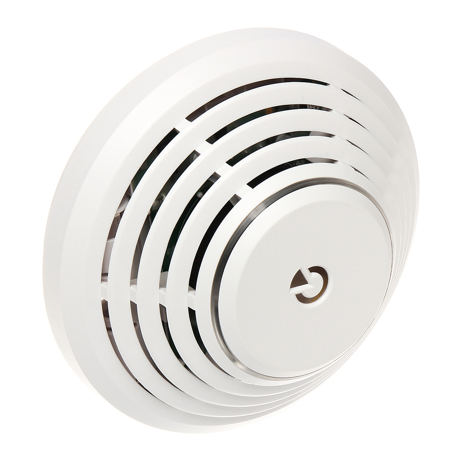
JA-111ST-A BUS combined smoke and heat detector
This device is a component of the JABLOTRON JA-100 alarm
system. It is used to detect fire hazards in the interior of residential
or commercial buildings. The detector is powered by the control panel
BUS (EN 54-7; EN 54-5). When the detector is powered by inserted
batteries (3x 1.5 V AA) and it loses BUS power or stops communicating
with its control panel, it can continue operating as a stand-alone
detector when the 12 V BUS power supply is disconnected
(EN 14604). Batteries are not included and we recommend buying them
with the detector.
The detector indicates a fire risk using the built-in LED indicator and
acoustic signalling. The detector can also indicate any other type
of alarm in the system such as intrusion or tampering.
The JA-111ST consists of two independent detectors – an optical
smoke detector and a heat detector. The optical smoke detector works
on the principle of scattered light. It is very sensitive to large dust
particles which are present in dense smoke. It is less sensitive
to smaller particles generated by the combustion of liquids such
as alcohol. That is why the fire detector also contains a built-in heat detector
which has a slower reaction but is much better at detecting fire which
generates only a small amount of smoke. The detector works in status
mode so it signals both activation and deactivation. The product is not
designed to be installed in industrial premises. The product should
be installed by a trained technician with a valid certificate issued
by an authorised Jablotron distributor.
Detector placement
The smoke detector must be installed so that any smoke easily drifts
into the detector owing to natural thermal currents, e.g. on the ceiling.
The detector can only be used in an enclosed interior. It is not suitable
for places where smoke can be dispersed or it can get cold (interiors
with extremely high ceilings above 5 m) - the smoke would not reach the
detector position.
The detector must always be placed in the section leading to the exit
of the building (escape route), see Fig. 1. If the building has a floor area
2
greater than 150 m
, installation of an additional detector in some other
suitable place is required, see Fig.2.
Fig 1
Fig 2
6
1
3
2
Fig 3
In multi-storey flats and family houses the detector should be installed
above the stairs. It is recommended to place additional detectors
in rooms where people sleep. See Fig 3.
Installation on level ceilings
Place the detector in the centre of the room if possible.
The detector must not be recessed into the ceiling due to the possible
existence of a cool air layer on the ceiling. Never place the detector
in the corner of the room (always keep at least 0.5 m distance from
the corner - see Fig 4). There is an insufficient circulation of air
in the corners.
Installation on sloping ceilings
If the ceiling is not suitable for mounting on a level surface
(e.g. a room under a roof ridge), the detector can be installed as in Fig. 5.
JA-111ST-A BUS combined smoke and heat detector
1. kitchen,
2. living room,
3. – 6. bedrooms
/
basic coverage
recommended coverage
Fig 4
centre of the room, best location
acceptable location
Walls, partitions, barriers and lattice ceilings
The JA-111ST-A detector must not be installed closer than 0,5 m
from any wall or partition. A narrow room with a width of less than 1,2 m
requires the detector(s) to be placed at a distance of at least one third of the
room's width away. In a case when a room is separated into sections with
walls, semi partition walls or furniture which do not reach the ceiling,
then each section must be consider as fully separated room if the gap
between the top of these and the ceiling does not exceed 0.3 m.
A free space of at least 0.5 m is required under and around the detector.
Any irregularities of the ceiling (e.g. girders) exceeding 5 % of the ceiling height
should be considered a wall and the above mentioned limitations should apply.
Ventilation and air circulation
The detectors must not be installed directly near ventilation or air
conditioning vents. In the case of air being supplied through
a perforated ceiling, each detector must be placed so that no perforation
hole occurs within 0.6 m of the detector.
Avoid installing the detector in the following places:
places
with poor air circulation (niches,
of A-shaped roofs, etc.)
places exposed to dust, cigarette smoke or steam
places with over-intense air circulation (close to ventilators, heat
sources, air conditioning outlets, etc.)
in kitchens and other cooking places (because steam, smoke or oily
fumes can cause false alarms or reduce detector sensitivity).
in areas with lots of small insects which can cause false alarms
Warning:
Most false alarms are caused by improper detector
See CEN/TS 54-14 standards for detailed installation guidelines.
Installation
When installing the detector, abide by the procedures recommended
in the previous paragraphs.
Fig 6: 1 – detector cover opening; 2 – detector cover closing;
3 – optical status signalling; 4 – arrow showing where to insert the detector;
5 – bus terminal; 6 – production code; 7 – battery holders
1. Open the detector cover, by turning it anti-clockwise (1)
2. Push the BUS cable through the base and attach the base
to the selected place using screws.
3. Connect the BUS cable.
4. When the device is switched on, the yellow LED on the PCB
inside the detector starts flashing repeatedly to indicate that
the detector has not been enrolled into the system.
When connecting the detector to the
system digital bus, always switch the
power off.
5. Proceed according to the control panel installation manual.
a. Go to the F-Link software, select the required position
in the Devices window and launch enrollment mode by clicking
on the Enroll option.
1 / 3
0,9 m
Fig 5
corners,
placement.
MLW21101
apexes
Advertisement
Table of Contents

Related Manuals for jablotron JA-111ST-A


Summary of Contents for jablotron JA-111ST-A
- Page 1 Walls, partitions, barriers and lattice ceilings The JA-111ST consists of two independent detectors – an optical The JA-111ST-A detector must not be installed closer than 0,5 m smoke detector and a heat detector. The optical smoke detector works from any wall or partition. A narrow room with a width of less than 1,2 m on the principle of scattered light.
- Page 2 JA-111ST-A BUS combined smoke and heat detector Batteries: Select the type of batteries used (*alkaline, lithium) b. Click to the option “Scan/add new BUS devices” and select this detector from the offered list and double-click to confirm or operating without batteries (the detector doesn´t check the status selection.
- Page 3 Do not throw used batteries into ordinary household waste. Deposit of them at authorized collection points. JABLOTRON ALARMS a.s. hereby declares that the JA-111ST-A is in a compliance with the relevant Union harmonisation legislation: Removal of the detector from the system Directives No: 2014/30/EU, 2011/65/EU.
Need help?
Do you have a question about the JA-111ST-A and is the answer not in the manual?
Questions and answers