Table of Contents
Advertisement
Installer's Guide
Convertible Air Handlers
1–1/2 — 5 Ton
A4AH6E19A1B30B
A4AH6E31A1B30B
A4AH6E43A1C30B
A4AH6E49A1C30B
A4AH6E61A1C30B
A4AH6V24A1B30B
A4AH6V30A1B30B
A4AH6V36A1C30B
A4AH6V42A1C30B
A4AH6V48A1C30B
A4AH6V60B1C30A
Only qualified personnel should install and service the equipment. The installation, starting up, and servicing of heating, ventilating, and air-conditioning
equipment can be hazardous and requires specific knowledge and training. Improperly installed, adjusted or altered equipment by an unqualified person
could result in death or serious injury. When working on the equipment, observe all precautions in the literature and on the tags, stickers, and labels that
are attached to the equipment.
February 2022
The A4AH6 series air handler is designed for installation in a closet,
utility room, alcove, basement, crawlspace or attic. These versatile
units are applicable to air conditioning and heat pump
applications. Several models are available to meet the specific
requirements of the outdoor equipment. Field installed electric
resistance heaters are available.
S S A A F F E E T T Y Y W W A A R R N N I I N N G G
1 1 8 8 - - G G F F 1 1 4 4 D D 1 1 - - 1 1 C C - - E E N N
Advertisement
Table of Contents

Subscribe to Our Youtube Channel
Related Manuals for Trane A4AH6E19A1B30B


Summary of Contents for Trane A4AH6E19A1B30B
- Page 1 Installer’s Guide Convertible Air Handlers 1–1/2 — 5 Ton A4AH6E19A1B30B A4AH6E31A1B30B A4AH6E43A1C30B A4AH6E49A1C30B A4AH6E61A1C30B A4AH6V24A1B30B A4AH6V30A1B30B A4AH6V36A1C30B A4AH6V42A1C30B A4AH6V48A1C30B A4AH6V60B1C30A The A4AH6 series air handler is designed for installation in a closet, utility room, alcove, basement, crawlspace or attic. These versatile units are applicable to air conditioning and heat pump applications.
- Page 2 SAFETY SECTION AIR HANDLERS I I m m p p o o r r t t a a n n t t : : This document contains a wiring diagram, W W A A R R N N I I N N G G a parts list, and service information.
- Page 3 S S A A F F E E T T Y Y S S E E C C T T I I O O N N A A I I R R H H A A N N D D L L E E R R S S W W A A R R N N I I N N G G N N o o t t e e : : Air handlers have been evaluated in accordance with the Code of Federal Regulations, Chapter...
-
Page 4: Table Of Contents
Table of Contents Features ........5 Heater Pressure Drop Table . -
Page 5: Features
Features Table 1. Standard Features Table 2. Optional Accessories • MULTI-POSITION UPFLOW, DOWNFLOW, HORIZONTAL LEFT • 4,5,8,10,15, 20 and 25 KW SINGLE PHASE ELECTRIC AND HORIZONTAL RIGHT HEATERS • PAINTED FINISH ON GALVANIZED STEEL EXTERIOR WITH Circuit breakers available on all single phase 4, 5, 8, 10, –... -
Page 6: Installation Instructions
Installation Instructions 1. U U n n p p a a c c k k i i n n g g 4. C C o o n n d d e e n n s s a a t t e e D D r r a a i i n n Carefully unpack the unit and inspect the contents The unit is supplied with primary and auxiliary for damage. - Page 7 I I n n s s t t a a l l l l a a t t i i o o n n I I n n s s t t r r u u c c t t i i o o n n s s Vent 9.
- Page 8 I I n n s s t t a a l l l l a a t t i i o o n n I I n n s s t t r r u u c c t t i i o o n n s s I I n n d d o o o o r r B B l l o o w w e e r r T T i i m m i i n n g g in conduit with power wiring and must be separated from power wiring unless class 1 wire...
- Page 9 I I n n s s t t a a l l l l a a t t i i o o n n I I n n s s t t r r u u c c t t i i o o n n s s Circuit R to O energizes the reversing valve to the H H e e a a t t i i n n g g ( ( e e l l e e c c t t r r i i c c h h e e a a t t o o n n l l y y ) ) cooling position.
-
Page 10: Field Wiring
Field Wiring Figure 4. Field Wiring Diagram — A4AH6E AC SYSTEMS HEAT PUMP SYSTEMS Outdoor Outdoor Thermostat Air Handler Thermostat Air Handler Unit Unit 24 VAC HOT 24 VAC HOT 24 VAC 24 VAC Common Common Blue Blue COOL/HEAT COOLING 1st STAGE HEATING HEAT... - Page 11 F F i i e e l l d d W W i i r r i i n n g g Figure 5. Field Wiring Diagram — A4AH6V —Single Stage Single Stage, Cooling Only Single Stage, HP Outdoor Outdoor Thermostat Air Handler Thermostat...
- Page 12 F F i i e e l l d d W W i i r r i i n n g g Figure 6. Field Wiring Diagram — A4AH6V —Two Stage 2 Stage, 2 Step, Cooling Only 2 Stage, 2 Step, HP Outdoor Outdoor Thermostat...
-
Page 13: Electrical Data
Electrical Data Figure 7. Electrical Schematic — A4AH6E* 18-GF14D1-1C-EN... - Page 14 E E l l e e c c t t r r i i c c a a l l D D a a t t a a Figure 8. Electrical Schematic — A4AH6V* 18-GF14D1-1C-EN...
-
Page 15: Performance And Electrical Data
Performance and Electrical Data Table 4. Air Flow Performance A4AH6E19A1B30B AIRFLOW EXTERNAL STATIC (in w.g) Speed Taps — 208 – 230 VOLTS High Med-High Med † Values are with wet coil, no filter, and no heaters CFM Correction for dry coil = Add 3% †... - Page 16 P P e e r r f f o o r r m m a a n n c c e e a a n n d d E E l l e e c c t t r r i i c c a a l l D D a a t t a a Table 6.
- Page 17 P P e e r r f f o o r r m m a a n n c c e e a a n n d d E E l l e e c c t t r r i i c c a a l l D D a a t t a a Table 8.
- Page 18 P P e e r r f f o o r r m m a a n n c c e e a a n n d d E E l l e e c c t t r r i i c c a a l l D D a a t t a a Table 10.
- Page 19 P P e e r r f f o o r r m m a a n n c c e e a a n n d d E E l l e e c c t t r r i i c c a a l l D D a a t t a a Table 11.
- Page 20 P P e e r r f f o o r r m m a a n n c c e e a a n n d d E E l l e e c c t t r r i i c c a a l l D D a a t t a a Table 12.
- Page 21 P P e e r r f f o o r r m m a a n n c c e e a a n n d d E E l l e e c c t t r r i i c c a a l l D D a a t t a a Table 14.
- Page 22 P P e e r r f f o o r r m m a a n n c c e e a a n n d d E E l l e e c c t t r r i i c c a a l l D D a a t t a a Table 15.
- Page 23 P P e e r r f f o o r r m m a a n n c c e e a a n n d d E E l l e e c c t t r r i i c c a a l l D D a a t t a a Table 17.
- Page 24 P P e e r r f f o o r r m m a a n n c c e e a a n n d d E E l l e e c c t t r r i i c c a a l l D D a a t t a a Table 18.
- Page 25 P P e e r r f f o o r r m m a a n n c c e e a a n n d d E E l l e e c c t t r r i i c c a a l l D D a a t t a a Table 20.
- Page 26 P P e e r r f f o o r r m m a a n n c c e e a a n n d d E E l l e e c c t t r r i i c c a a l l D D a a t t a a Table 21.
- Page 27 P P e e r r f f o o r r m m a a n n c c e e a a n n d d E E l l e e c c t t r r i i c c a a l l D D a a t t a a Table 23.
-
Page 28: Minimum Airflow Cfm
Minimum Airflow CFM A4AH6E19A1B30B Minimum Heat Speed Tap Heater With Heat Pump Without Heat Pump BAYHTR1504BRK, BAYHTR1504LUG, BAYHTR1505BRK, BAYHTR1505LUG BAYHTR1508BRK, BAYHTR1508LUG, High BAYHTR1510BRK, BAYHTR1510LUG, BAYHTR3510LUG A4AH6E31A1B30B Minimum Heat Speed Tap Heater With Heat Pump Without Heat Pump BAYHTR1504BRK, BAYHTR1504LUG, BAYHTR1505BRK, BAYHTR1505LUG... - Page 29 M M i i n n i i m m u u m m A A i i r r f f l l o o w w C C F F M M A4AH6V24A1B30B, A4AH6V30A1B30B Heater Minimum Heater Airflow CFM With Heat Pump Without Heat Pump BAYHTR1504BRK, BAYHTR1504LUG...
- Page 30 M M i i n n i i m m u u m m A A i i r r f f l l o o w w C C F F M M A4AH6V30A1B30B Airflow Performance with Auxiliary Heat Dip Switch Settings Airflow Settings Nominal Airflow...
-
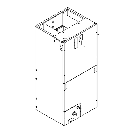
Page 31: Outline Drawing
Outline Drawing NOTE: THIS UNIT IS APPROVED FOR INSTALLATION CLEARANCES TO COMBUSTIBLE MATERIAL AS STATED ON THE UNIT RATING NAMEPLATE NOTE: ALL DIMENSIONS ARE REFERENCE DIMENSIONS PRODUCT DIMENSIONS Flow Gas Line Air Handler Model Control Braze A4AH6E19 45.02 18.50 16.50 16.75 4.68 7.33... -
Page 32: Heater Pressure Drop Table
Heater Pressure Drop Table Number of Racks Heater Racks Airflow Heater Model No. of Racks Air Pressure Drop — Inches W.G. BAYHTR1504 1800 0.02 0.04 0.06 0.14 BAYHTR1505 1700 0.02 0.04 0.06 0.14 BAYHTR1508 1600 0.02 0.04 0.06 0.13 BAYHTR1510 1500 0.02 0.04... -
Page 33: Coil Conversion Instructions
Coil Conversion Instructions Table 24. Downflow Figure 9. All models Follow the conversion steps when installing the air handler in downflow configuration. Remove the front panels from the air handler. The coil and line set panel do not need to be separated. Remove the fasteners on both sides of the coil. - Page 34 C C o o i i l l C C o o n n v v e e r r s s i i o o n n I I n n s s t t r r u u c c t t i i o o n n s s Table 24.
- Page 35 C C o o i i l l C C o o n n v v e e r r s s i i o o n n I I n n s s t t r r u u c c t t i i o o n n s s Table 24.
-
Page 36: Coil Conversion
C C o o i i l l C C o o n n v v e e r r s s i i o o n n I I n n s s t t r r u u c c t t i i o o n n s s Coil Conversion Table 25. - Page 37 C C o o i i l l C C o o n n v v e e r r s s i i o o n n I I n n s s t t r r u u c c t t i i o o n n s s Table 25.
- Page 38 C C o o i i l l C C o o n n v v e e r r s s i i o o n n I I n n s s t t r r u u c c t t i i o o n n s s Figure 20.
- Page 39 C C o o i i l l C C o o n n v v e e r r s s i i o o n n I I n n s s t t r r u u c c t t i i o o n n s s Figure 24.
- Page 40 C C o o i i l l C C o o n n v v e e r r s s i i o o n n I I n n s s t t r r u u c c t t i i o o n n s s Figure 28.
- Page 41 C C o o i i l l C C o o n n v v e e r r s s i i o o n n I I n n s s t t r r u u c c t t i i o o n n s s Figure 32.
- Page 42 C C o o i i l l C C o o n n v v e e r r s s i i o o n n I I n n s s t t r r u u c c t t i i o o n n s s Figure 36.
-
Page 43: Checkout Procedures
Checkout Procedures The final phase of the installation is the system Checkout Procedures. The following list represents the most common items covered in a Checkout Procedure. Confirm all requirements in this document have been met. ☐ All wiring connections are tight and properly secured. ☐... - Page 44 About Trane and American Standard Heating and Air Conditioning Trane and American Standard create comfortable, energy efficient indoor environments for residential applications. For more information, please visit www.trane.com or www.americanstandardair.com. The manufacturer has a policy of continuous data improvement and it reserves the right to change design and specifications without notice. We are committed to using environmentally conscious print practices.
Need help?
Do you have a question about the A4AH6E19A1B30B and is the answer not in the manual?
Questions and answers