Advertisement
Quick Links
V1
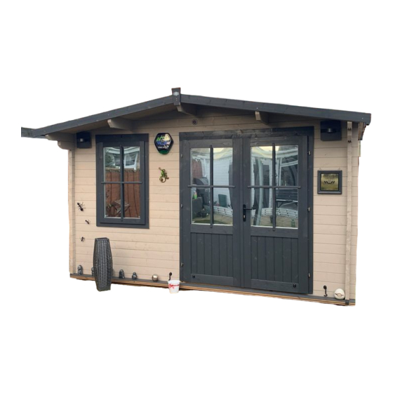
RHINE 4.0m x 5.0m ( 45mm ) Log Cabin
E10-4050R-45
Installation Manual
Please read this installation manual carefully
before proceeding with the construction of your log cabin.
Check all components prior to assembly
If you have purchased a log cabin with an extension please refer to the extension manual set
Important!
All dimensions are approximate and subject to the limitations of the materials used and the methods of manufacture
Unique Cabin Reference Number
Construction videos link
_____________________________
www.dunsterhouse.co.uk
Advertisement

Related Manuals for Dunster House RHINE


Summary of Contents for Dunster House RHINE
- Page 1 RHINE 4.0m x 5.0m ( 45mm ) Log Cabin E10-4050R-45 Installation Manual Please read this installation manual carefully before proceeding with the construction of your log cabin. Check all components prior to assembly If you have purchased a log cabin with an extension please refer to the extension manual set...
- Page 2 Parts List Page 2 WOODEN PARTS : including 1 extra wall log, 1 extra floor board, and 2 extra roof boards PART NUMBER DESCRIPTION THK_mm WIDTH_mm LNG_mm EN.3850 Bearer ( Pressure treated ) 3850 F.4760 4760 Floor Board T&G F.2080 Roof Board T&G 2080 A45.5240.70.320.0...
- Page 3 • Dunster House Ltd will not freely replace any parts that are damaged due to any neglectful workmanship when your cabin is being built. However, replacement parts are available to purchase, please contact our Parts department at parts@dunsterhouse.co.uk.
- Page 4 If you are still unable to find an answer to your query please contact our Customer Services department by email or in writing stating your query and including your order number starting with "SO" or your postcode to either: cs@dunsterhouse.co.uk or FAO Customer Services, Dunster House Ltd - Factory 1, Elms Farm Industrial Estate, Bedford, MK41 0LF Assembly Instruction Instructions are available from our website - https://dunsterhouse.co.uk/customer-login-area/log-in.
- Page 5 Page 5 How to install twisted/warped timber Timber is a natural product and unlike extrusions made from plastic or metal is likely to twist due to the nature of the material. Warped timber is unavoidable particularly with soft wood and is more common in longer and larger sections. Warping can occur even once a product is packed.
- Page 6 Component List Page 6 BEARERS BOTTOM WALL LOG Pressure Treated ITEM QTY PART NUMBER DESCRIPTION THK_mm WIDTH_mm LNG_mm ITEM QTY PART NUMBER DESCRIPTION THK_mm WIDTH_mm LNG_mm B45.1805.70.0.0 Bottom Wall Log 64.5 1805 EN.3850 Bearer ( Pressure treated ) 3850 B45.505.70.0.0 Bottom Wall Log 64.5 BOTTOM WALL LOG...
- Page 7 Component List Page 7 WALL LOG ITEM QTY PART NUMBER DESCRIPTION THK_mm WIDTH_mm LNG_mm A45.5240.70.320.0 Wall Log 5240 TOP WALL LOG - Right ITEM QTY PART NUMBER DESCRIPTION THK_mm WIDTH_mm LNG_mm XN45.8R.5490.70.570.0 Top Wall Log Right 5490 TOP WALL LOG - Left ITEM QTY PART NUMBER DESCRIPTION...
- Page 8 Component List Page 8 PURLIN Reinforced Middle ITEM QTY PART NUMBER DESCRIPTION THK_mm LNG_mm P45.5490.65.565.0 Purlin + Purlin Support 5490 PURLIN Reinforced Left ITEM QTY PART NUMBER DESCRIPTION THK_mm LNG_mm P45.5490.65.565.0 Purlin + Purlin Support 5490 PURLIN Reinforced Right ITEM QTY PART NUMBER DESCRIPTION THK_mm...
- Page 9 Component List Page 9 APEX The image used is for reference only, the number of purlin cut outs may vary on your cabin apex. See the wall layout page for details of your specific apex. ITEM QTY PART NUMBER DESCRIPTION THK_mm HT_mm LNG_mm...
- Page 10 First Wall Logs Page 10 ITEM QTY PART NUMBER DESCRIPTION IMPORTANT - Ensure that the base of the bearers and first layer of A45.4990.70.70.0 Wall Log wall logs are level and square. Continue to check if the cabin is B45.3990.70.70.0 Bottom Wall Log square by measuring the diagonals and that the walls are level B45.505.70.0.0...
- Page 11 Wall Layout Page 11 The layout of your doors and windows can be changed by installing the relevant logs on the opposite side of the cabin or the Front Wall opposite side of the front wall. The position of the XN logs cannot be changed and need to have the top angle sloping outwards from the middle of the cabin.
- Page 12 Wall Layout Page 12 The layout of your doors and windows can be changed by installing the relevant logs on the opposite side of the cabin or Side Wall - Left the opposite side of the front wall. The position of the XN logs cannot be changed and need to have the top angle sloping outwards from the middle of the cabin.
- Page 13 Doors & Windows Page 13 ITEM QTY PART NUMBER The windows are pre-assembled but the door frame for your cabin comes E10 - STANDARD GLASS DOUBLE DOOR - 45 in separate parts to protect it during transportation. Please note that the E10 - STANDARD WINDOW - 45mm bottom part will be slotted together with the top part to prevent damage during transport.
- Page 14 Do not tighten the screw fully, this will allow the frames enough freedom of movement to realign vertically but stay in position horizontally. Attach the Dunster House logo plate to hide the screw and slotted hole when the frame is fitted.
- Page 15 Doors & Windows - additional information Page 15 Georgian bar & Drip bar Door sashes Door bolts Pre-drill 3mm pilot holes for all screws to avoid With the cabin assembled and the door frame in place Note: Before proceeding with the installation of splitting timbers.
- Page 16 Top Wall Logs Page 16 ITEM QTY PART NUMBER DESCRIPTION IMPORTANT - Check the cabin is square and the walls are level. A45.3990.70.70.0 Wall Log A45.505.70.0.0 Wall Log IMPORTANT - Use a step ladder to install the top wall logs, and A45.5240.70.320.0 Wall Log A45.1805.70.0.0...
- Page 17 Purlins Page 17 ITEM QTY PART NUMBER DESCRIPTION THK_mm WIDTH_mm LNG_mm IMPORTANT - Check the cabin is square and the walls are level. P45.5490.65.565.0 Purlin + Purlin Support 5490 IMPORTANT - Use a step ladder to install the purlins and roof boards. Do not put your weight on the roof before all roof boards are secured.
- Page 18 Roof Installation Page 18 ITEM QTY PART NUMBER DESCRIPTION IMPORTANT - The optional Roof Insulation is installed after the roof boards, F.2080 Roof Board T&G please refer to the "Roof Insulation (optional)" section in this manual. J.1960 Trim ROOF BOARDS Roof Boards - F •...
- Page 19 a i t Page 19 ITEM QTY PART NUMBER THK_mm WIDTH_mm LNG_mm Install roof insulation on top of the roof boards, but ROOF INSULATION P2-PANEL A 2500x1250 1250 2500 prior to installing felt or shingles. Pre-drill 3mm ROOF INSULATION P2-PANEL K 2500x415 2500 pilot holes for all screws to avoid splitting Roof Insulation L Bracket...
- Page 20 Roof Felt Page 20 Waterproof membrane Roof felt IMPORTANT - Roof Insulation should be installed prior to felt. See the Roof Insulation page for details. 40-50mm overhang • The Eaves Edging and Eaves Edge Reinforcement must be fitted before the waterproof membrane Eaves Roof boards edging...
- Page 21 Shingles (Rectangular) Page 21 Fig. A First layer of rectangular shingles, with the slots Cutting line IMPORTANT - Roof Insulation should be installed prior to pointing towards the roof ridge Fig. D Rectangular Shingles shingles. See the Roof Insulation page for details. •...
- Page 22 Roof Installation Page 22 ITEM QTY PART NUMBER DESCRIPTION It is essential you fit a waterproof covering to the roof. Eaves Edging J.1960 Trim is fitted before any roof covering, the Fascia Boards after. Before HN.3000 Eaves Edging following the next steps, please read the "Felt installation" or Z.120.A Trapezoid "Shingles installation"...
- Page 23 Storm Braces and Vents Page 23 ITEM QTY PART NUMBER DESCRIPTION THK_mm WIDTH_mm LNG_mm STORM BRACES J.1960.B Storm Brace 1960 • Storm braces should be installed after the roof is fitted. VENTS - SET Vent Set • Storm braces can be installed internally or externally. •...
- Page 24 Floor Installation Page 24 ITEM QTY PART NUMBER DESCRIPTION THK_mm WIDTH_mm LNG_mm FLOOR BOARDS J.1960 Trim 1960 F.4760 Floor Board T&G 4760 • We recommend that the floor boards are installed when the cabin walls and roof are completed. • Place the floor boards centrally between the front and rear walls and Floor Boards - F at right angles to the bearers.
- Page 25 Position the hole/screw towards the top of the slotted hole. Do not tighten the screw fully. This will allow the frames enough freedom of movement to realign vertically if the wall logs 'move' but stay in position horizontally. See the Door And Window Installation page of this manual for more information. Attach the Dunster House logo plate to hide the slotted hole and screw, when the frame is secured.
Need help?
Do you have a question about the RHINE and is the answer not in the manual?
Questions and answers