Table of Contents
Advertisement
Quick Links
Advertisement
Table of Contents

Subscribe to Our Youtube Channel
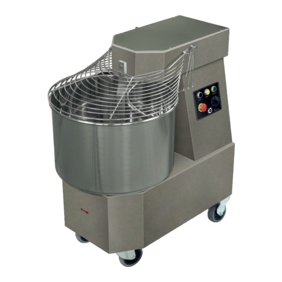
Summary of Contents for Cuppone VENERE 10
- Page 1 V E N E R E Mixer 10/20/30 PREINSTALLATION INSTALLATION...
-
Page 2: Table Of Contents
Serial number plate reading ........................10 installation. Electrical connection ............................ 11 Do not hesitate to contact him in case of doubt. Belt tension adjustment ..........................12 CUPPONE since 1963 Installation | Electrical diagrams ......................13 CUPPONE S.R.L. Via Sile, 36 31057 Silea (TV) - ITALY FINAL OPERATIONS ...................... -
Page 3: Checks Before Purchasing
C H E C KS B E F O R E PU R C H A S I N G Before purchasing the product and installing it, check Fig.1 Fig.2 ■ there are NO other sources of heat the following conditions, necessary for the correct instal- (i.e. -
Page 4: Technical Data
Customer Power supply Absorption Cable type speed power speed power panel protection Model (kW) (kW) (N x mm VENERE 10 3N x 400 V 0.55 0.75 4x0.75 3x16 VENERE 20 3N x 400 V 4x0.75 3x16 VENERE 30 3N x 400 V 4 x 0.75... - Page 5 Te c h n i c a l d a t a | O ve r a l l d i m e n s i o n s VENERE 10 VENERE 20 710 mm [28”] ø350 mm [ø13,77”] ø420 mm [ø16,5”] 580 mm [22,83”]...
-
Page 6: Before The Installation, Read The Content Of This Manual Technical Data | Overall Dimensions
Te c h n i c a l d a t a | O ve r a l l d i m e n s i o n s VENERE 30 780 mm [30,7”] ø480 mm [ø18,9”] bowl diameter 452 mm [17.8"] bowl height 260 mm [10.2"] bowl capacity... -
Page 7: Safety Instructions
S A F E TY I N S T R U C T I O N S SYMBOLS USED IN THE MANUAL • Read this guide carefully before install- manual may cause damage, injury or ing the appliance, and keep it with care AND ON THE LABELS APPLIED TO fatal accidents. -
Page 8: Symbols Applied To The Machine
S a f e t y i n s t r u c t i o n s SYMBOLS APPLIED TO THE MACHINE NOTES Do not remove the guard Electricity hazard Hand crushing hazard Gears danger The company cannot be held liable for any print or transcrip- tion errors, reserving the right to make changes where deemed suitable without prior notice. -
Page 9: Installation
I N STA L L AT I O N TRANSPORT Fig.5 Fig.6 Fig.5 Equipped with personal protection equipment, trans- port the appliance to the installation location. Use a suitable vehicle capable of withstanding the weight of the same. Persons not involved with the appliance instal- lation may not pass through or stand in the work area during the transport of the appliance. -
Page 10: Positioning
I n s t a l l a t i o n POSITIONING Fig.8 Name and address of the Manufacturer Fig.7 Model Install the appliance in a room: Electrical parameters ■ dedicated and suitable to the cooking of food; ■ having adequate air ventilation;... -
Page 11: Electrical Connection
I n s t a l l a t i o n ELECTRICAL CONNECTION earth The electrical connection must be carried out F - R - S - T...L: exclusively by qualified personnel after read- phases ing the safety warnings at the beginning of the manual. -
Page 12: Belt Tension Adjustment
I n s t a l l a t i o n Fig.10 After connection, make sure that the cable: Fig.11 Fig.10 ■ is not hindering the passage of people or objects (e.g. trolleys on wheels); ■ is not crushed or bent; ■... -
Page 13: Installation | Electrical Diagrams
I n s t a l l a t i o n | E l e c t r i c a l d i a g r a m s Abbreviation Description Contactor Motor Transformer Fuse LAMP Light Thermal relay Timer STOP Emergency button... -
Page 14: Final Operations
F I N A L O P E R AT I O N S PRE-TESTING AND FINAL INSPECTION The product is checked and tested in the Manufacturer’s plant before being delivered to the customer. The “production process check sheet” enclosed with it guarantees that each step in the production process, from assembly to packaging, was carefully checked from both the operating and safety standpoints. -
Page 15: Checking The Correct Direction Of Rotation Of The Bowl
F i n a l o p e r a t i o n s CHECKING THE CORRECT DIRECTION OF ROTATION OF THE BOWL Fig.13 Fig.13 Make sure that the bowl rotates in the direction of the arrow. If this condition is not met, reverse two phases (e.g.


Need help?
Do you have a question about the VENERE 10 and is the answer not in the manual?
Questions and answers