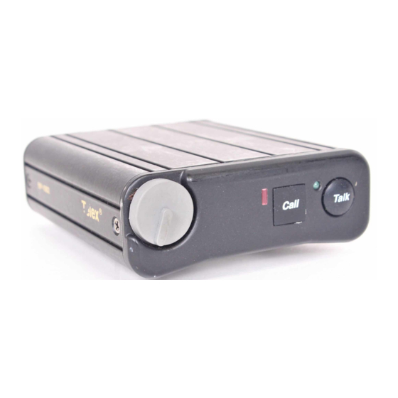
Telex BP-1002 Operating Instructions Manual
Beltpacks audiocom intercom system
Hide thumbs
Also See for BP-1002:
- Operating instructions manual (24 pages) ,
- Operating instructions manual (19 pages) ,
- Operating instructions manual (20 pages)
Summary of Contents for Telex BP-1002
- Page 1 Telex Operating Instructions BP-1002/BP-2002 Beltpacks Audiocom ® Intercom System 93507740000 Rev H 12/2005...
-
Page 2: Factory Service
In lieu of this, you may obtain a Return Authorization form from our Customer Service Department. Customer Service Department Telex Communications, Inc. 12000 Portland Avenue South Burnsville, Minnesota 55337 U.S.A. Telephone: (800) 392-3497... -
Page 3: Fcc Statement
Operation of this equipment in a residential area may cause interference which the user (at his own expense) will be required to correct. ® Audiocom is a registered trademark of Telex Communications, Inc., Burnsville, Minnesota 55337 ® Clear-Com is a registered trademark of Clear-Com Intercom Systems... - Page 4 TO PREVENT DAMAGE TO THE EQUIPMENT, THESE MODIFICATIONS SHOULD ONLY BE MADE BY QUALIFIED TECHNICIANS. If desired, the Mic-Kill and Call signal features can be disabled in the BP-2002/BP-1002 by removing a surface-mounted capacitor from the printed circuit board. Perform the following: Before making changes to the printed circuit board, disconnect all power and line connections from the beltpack.
-
Page 5: Operation
The BP-1002 belt pack receives power externally, via the intercom channel. Both the BP-1002 and BP-2002 will pass system power through to subsequent belt packs that are “daisy chained” together. The channel termination is initially set for balanced operation, which is compatible with other Audiocom®... -
Page 6: Specifications
Figure 1. BP-2002 & BP-1002 Connections and Controls SPECIFICATIONS GENERAL: Power Requirements: Channel supplied: 24 VDC nominal, 45 to 70 mA Local-power: (BP-2000 only) 24 VDC nominal (18 to 30 VDC), 45 to 70 mA Environmental Requirements: Storage: -20ºC to 80ºC; 0% to 95% humidity,... - Page 7 Pin 3 Headphone high Pin 4 Headphone low Intercom Channel Connectors BP-1002 Type: One XLR-3M and XLR-3F pair (callout 8 in Figure 1) Audiocom ® Mode (Internal switch SW1 and jumpers JP4, JP5, JP2 and JP1 set to BAL position)
- Page 8 Then, use a small flat-blade screwdriver to increase or decrease your voice level while talking into themicrophone. (This control is accessible by removing one screw of belt clip.) 6. H : This connector accepts a four-wire Telex® boom-microphone EADSET ONNECTOR headset.
- Page 9 NOTE: On the BP-1002, jumper JP6 must always have pins 2 and 3 shorted. Side Tone Adjustment (R145) The side tone adjustment is accessible either internally (refer to Figure 2) or by removing the belt clip mounting screw (callout 5 in Figure 1).
- Page 10 3. Press the Call key to change to the next mode of operation. Each press of the Call key will cause the BP-1002/BP-2002 to change to the next mode of operation. 4. When the desired mode is reached, press the Talk key to select that mode and exit the mode changing function.


Need help?
Do you have a question about the BP-1002 and is the answer not in the manual?
Questions and answers