Table of Contents
Advertisement
Quick Links
User Instruction & Installation Manual
Product Reference Number:
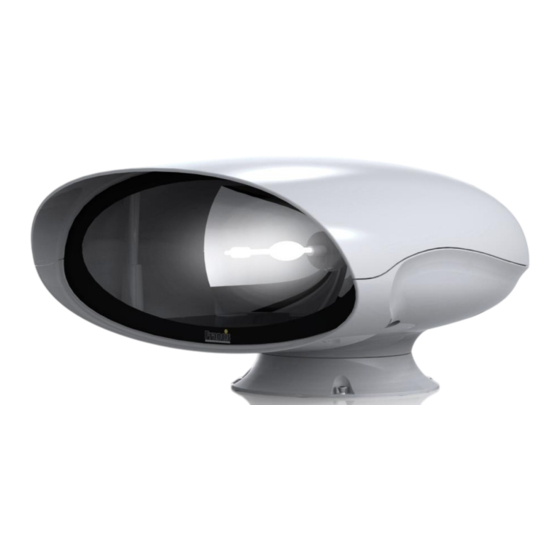
A7182 VM500 350w 115/230v Em-Arc Glass Reflector
A7189 VM500 350w 115/230v Em-Arc Aluminium Reflector
Manufacturer's details:
Francis Searchlights Ltd
Union Road, Bolton
Lancashire, BL2 2HJ, UK
Tel:
+44 (0) 1204 558960
Fax:
+44 (0) 1204 558979
http://www.francis.co.uk
E-mail: sales@francis.co.uk
Manual Part Number: C27394
Issue: 3
18/4/18
Distributor details:
Advertisement
Table of Contents

Subscribe to Our Youtube Channel
Related Manuals for Francis Searchlights A7182 VM500


Summary of Contents for Francis Searchlights A7182 VM500
- Page 1 User Instruction & Installation Manual Product Reference Number: A7182 VM500 350w 115/230v Em-Arc Glass Reflector A7189 VM500 350w 115/230v Em-Arc Aluminium Reflector Manufacturer’s details: Distributor details: Francis Searchlights Ltd Union Road, Bolton Lancashire, BL2 2HJ, UK Tel: +44 (0) 1204 558960...
-
Page 2: Table Of Contents
CONTENTS - Introduction - Safety Precautions - Technical Information - Unpacking and Installation Instructions - Electrical Installation - Operating Instructions - Fault Finding - Maintenance and Servicing - Wiring Diagrams & General Assembly - Spare Parts List... -
Page 3: Introduction
For your future reference please keep this manual in a safe place. Thank you for specifying a product from the Francis Searchlights range. All Francis products are designed to give complete customer satisfaction and are manufactured to the highest engineering standards in order to ensure optimum performance and service life. -
Page 4: Safety Precautions
2 - Safety Precautions The following instructions must be adhered to, in order to ensure a safe working environment and the safety of the user. Note: When unpacking or manoeuvring the searchlight into its fixing position, suitable lifting points must be used in order to prevent damage to the equipment or personal injury. -
Page 5: Technical Information
3 - Technical Information This product has been designed to operate in accordance with the product specification. The VM500 RC searchlight has the following features: ◼ All marine grade materials and fixings; ◼ Electronic power supply unit; ◼ Parabolic glass or aluminium reflector; ◼... -
Page 6: Unpacking And Installation Instructions
4 - Unpacking and Installation Instructions The following instructions should be read and fully understood prior to installing the equipment to ensure that the correct procedures are followed, and all safety precautions are observed. Note: If the equipment has been in storage for a considerable amount of time, it is advisable to conduct a routine maintenance check on all parts before installation. -
Page 7: Electrical Installation
5 - Electrical Installation Note: ~ When the main power is first applied to the searchlight, the searchlight will carry out a self-test, it will Pan to the left limit and Tilt down to the limit, once this is complete, the searchlight will then move to the centre and horizontal, during this please do not try and operate the searchlight while this test is being carried out. -
Page 8: Operating Instructions
6 - Operating Instructions This equipment is designed for use out of doors, in free air. Never place anything on or cover the searchlight when in use as this may present a hazard. Switch On The panel is activated using the PANEL button. This will illuminate brightly when the panel is active. - Page 9 Clear Motion Limits Motion limits as set above can be cleared by switching the panel off then pressing and holding the focus button and lamp buttons together for 10 seconds. Adjusting Panel Illumination The panel illumination and indicators intensity can be adjusted to suit ambient light levels. To adjust the intensity, switch the panel on then switch it off with the PANEL button and keep the PANEL button pressed.
- Page 10 8. Limit Switch Error. Some lamp types do not use all or some limit switches. If an invalid limit switch input is detected it is probable the speed control card is set to the wrong product or there is a wiring error. 9.
- Page 11 Always isolate the equipment from the supply when fitting a lamp See next sheet for fitting aid diagram Before fitting the lamp: Loosen and remove five M8 socket bolts with the dubo washer on the underneath of the searchlight, then remove the upper hood off the searchlight & store along with the bolts and washers in a safe area;...
- Page 13 Release the M4 knurled nut and spring washer that secures the front lead to the positive end of the lamp. + Positive end of the lamp (FRONT) M4 knurled nut and spring washer Keep the knurled nut and washer in a safe place as it will be needed later.
- Page 14 FBUS SPEED CONTROL ASSEMBLY DETAILS MAINS CONNECTORS Live. Neutral Earth TILT CONNECTOR Tilt Motor Red Wire (+) Tilt Motor Black Wire (-) Tilt Encoder Red Wire (5V). (Voyager Brown Wire) Tilt Encoder Green Wire (Phase A Output) (Voyager Yellow Wire) Tilt Encoder White Wire (Phase B Output) Tilt Encoder Black Wire (Voyager Blue Wire) Tilt Limit Switch Common Black Wire...
- Page 15 FBUS Speed Control Board...
- Page 16 CONNECTIONS TO FBUS JOYSTICK CONTROL PANEL FBUS CONNECTOR OV Supply Input Line Terminate (Connect to + for terminate) FBUS + RS485 Data In/Out FBUS - RS485 Data In/Out +24V Supply Input JOYSTICK CONNECTOR Joystick Black Wire Joystick Yellow Wire Joystick Blue Wire Joystick Red Wire FBUS JOYSTICK CONTROL BOARD...
- Page 17 FBUS ADDRESS SWITCHES OVERVIEW FBUS uses two types of address switch. One type is rotary, and the value selected is the value shown on the dial. The other type is rows of switches whose operation is described below: - The switches all operate in the same manner producing a binary value with the highest binary value to the left and the lowest value to the right.
- Page 18 EXAMPLES Standard control panel – panel address set to 5 Switch 1 = Off Switch 2 = On (Value 4 added to address) Switch 3 = Off Switch 4 = On (Value 1 added to address) 4 + 1 = 5 Speed control card - lamp address set to 11 Switch 4 = Off Switch 5 = On (Value 8 added to address)
- Page 19 FBUS DATA PROTOCOL OVERVIEW The Francis bus (FBUS) is a custom communication protocol based on RS485 two wire bi directional communication hardware. The system provides a simple bi-directional link between lamps and lamp control panels. The system allows given panels to communicate with different lamps and also allows a number of panels to communicate with the same lamp.
- Page 20 PANEL TRANSMITTED DATA Panels only send data when there is data to be sent i.e. there has been activity at the panel which must be sent to a given lamp. If there is no data to be sent, a panel will not transmit. The amount of data a panel sends will depend upon the amount of activity at the panel and can be 2 to 10 bytes.
- Page 21 DATA_FOCUS_BUTTON (Hex 0B) This is a single byte command. When the lamp receives this, it will run the focus motor as long as the command remains. A panel will send this command so long as the focus button is pressed. DATA_HOME_BUTTON (Hex 0C) This is s single byte command.
- Page 22 DATA_TILT_POSITION (Hex 19) This is a three-byte command. Following the DATA_TILT_POSITION command two data bytes specify the position to which the lamp must move. The bearing resolution is 0.1 degrees. The value is sent LSB first with the first byte representing the lower position command bits. The MSB (sent last) lower 4 bits represents the remaining value.
- Page 23 The CRC is a simple data checking system. Basically, this is just the sum of the lamps address and bytes above. The value is radix to 8 bits. If the lamp address was 0 (bus address value 16) and the pan and tilt were both at centre and the lamp was switched on and all other status bits were 0 the values would be Hex 110, 80, 80, 01.
- Page 24 RECEIVING FROM A LAMP Lamps broadcast data sequentially. There is no need to actively request data to be sent, just wait for the lamps address with bit 7 set to be present on the bus and load the next six bytes. An example is given below; - EXAMPLE Obtain lamp number 2 pan position.
- Page 25 1. Pan Limit. – Either of the pan limit switches operated. Note that this may not actually be a fault. The LED will flash when a limit switch is operated under normal circumstances i.e. the lamp is at the limit of travel.
- Page 26 FBUS INTERFACE UNIT (if supplied) OVERVIEW Francis Searchlights FBUS system is designed to allow multiple control panels to manage a number of searchlights on a common data cable. The data system is application specific and, as such, has a fixed data rate and complex timing.
- Page 27 SET PANEL ADDRESS The FBUS interface looks like a standard control panel to the FBUS as such it must have a panel address. The panel address must not be set to the same value as any other panel on the system. Panel addresses start at 0 and go up to 15.
- Page 28 FAULTS+LIMITS This displays any faults or limit switch activation relating to the selected lamp. Multiple faults will be displayed sequentially. LAMP SOFTWARE This displays the software version of the currently selected lamp LAMP TYPE No This displays the lamp type number. EXT COMMS DATA This item is included to aid external interface development.
- Page 29 DATA_PAN_CLOCKWISE (0x14) This is a five-byte command (Sync, Lamp address, command, speed, CRC) The speed value is between 0 and 127. Value 0 stops pan motion. Increasing values make the lamp move progressively faster. Transmitting codes 0xFF 0x90 0x14 0x7F would make lamp 0 move full speed clockwise. DATA_PAN_ANTICLOCKWISE (0x15) This is a five-byte command (Sync, Lamp address, command, speed, CRC) The speed value is between 0 and 127.
- Page 30 DATA_LAMP_ON (0x1A) This is a four-byte command (Sync, Lamp address, command, CRC). The lamp will switch on when this code is received. DATA_LAMP_OFF (0x1B) This is a four-byte command (Sync, Lamp address, command, CRC). The lamp will switch off when this code is received. DATA_RECORD (0x0D) This is a four-byte command (Sync, Lamp address, command, CRC).
- Page 31 ERROR CONTROL Error control is supported by a CRC following each data packet. The CRC is radix to 7 bits with a value between 0 and 127. The CRC is simply the addition of all packets data values including the address and start byte (0xFF). For example, if lamp 0 were commanded to run its focus motor the transmitted data would be;...
-
Page 32: Fault Finding
7 - Fault Finding All fault finding must be conducted by a competent person or qualified Electrical Engineer. Failure of Lamp to light Causes: 1) Power not supplied; 2) Fuse blown; 3) Failed lamp Remedy: 1) Check voltage at supply. If supply is not present the fault is at the customer supply. If power is present, see remedy 2;... -
Page 33: Maintenance And Servicing
8 - Maintenance and Servicing In order to prolong the service life and performance of your searchlight, the following maintenance guidelines are recommended: ◼ Maintenance checks should be conducted before every voyage or at least every three months; ◼ Before checking, disconnect the equipment from the supply; ◼... -
Page 34: Wiring Diagrams & General Assembly
9 - Wiring Diagrams and General Assembly Drawing Number Description A7180 A7182 VM500 G.A C27386 Wiring Diagram C27312 Joystick Control Panel C27381 Junction Box Assembly... -
Page 39: Spare Parts List
Joystick Controller PCB In order to prolong the life and performance of your product, we recommend that you only specify Francis Searchlights spare parts. This will ensure that any warranties on your equipment will not be invalidated. When ordering spare parts, please contact the Sales Department at Francis Searchlights Ltd.
Need help?
Do you have a question about the A7182 VM500 and is the answer not in the manual?
Questions and answers