Table of Contents
Advertisement
Quick Links
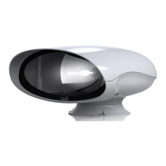
User Instruction & Installation Manual
Product Reference Number:
A7180 VH500 250w 24v Halogen
A7181 VH500 250w 110v/230v Halogen
Manufacturer's details:
Francis Searchlights Ltd
Union Road, Bolton
Lancashire, BL2 2HJ, UK
Tel:
+44 (0) 1204 558960
Fax:
+44 (0) 1204 558979
http://www.francis.co.uk
E-mail: sales@francis.co.uk
Manual Part Number: C27395
Issue: 2
18/4/18
Distributor details:
Advertisement
Table of Contents

Related Manuals for Francis Searchlights A7180 VH500


Summary of Contents for Francis Searchlights A7180 VH500
- Page 1 User Instruction & Installation Manual Product Reference Number: A7180 VH500 250w 24v Halogen A7181 VH500 250w 110v/230v Halogen Manufacturer’s details: Distributor details: Francis Searchlights Ltd Union Road, Bolton Lancashire, BL2 2HJ, UK Tel: +44 (0) 1204 558960 Fax: +44 (0) 1204 558979 http://www.francis.co.uk...
-
Page 2: Table Of Contents
CONTENTS - Introduction - Safety Precautions - Technical Information - Unpacking and Installation Instructions - Electrical Installation - Operating Instructions - Fault Finding - Maintenance and Servicing - Wiring Diagrams & General Assembly - Spare Parts List... -
Page 3: Introduction
For your future reference please keep this manual in a safe place. Thank you for specifying a product from the Francis Searchlights range. All Francis products are designed to give complete customer satisfaction and are manufactured to the highest engineering standards in order to ensure optimum performance and service life. -
Page 4: Safety Precautions
2 - Safety Precautions The following instructions must be adhered to, in order to ensure a safe working environment and the safety of the user. Note: When unpacking or manoeuvring the searchlight into its fixing position, suitable lifting points must be used in order to prevent damage to the equipment or personal injury. -
Page 5: Technical Information
3 - Technical Information This product has been designed to operate in accordance with the product specification. The VH500 searchlight has the following features: ◼ All marine grade materials and fixings; ◼ Parabolic glass reflector; ◼ 350° horizontal rotation; ◼ Vertical movement +20° to -20°; ◼... -
Page 6: Unpacking And Installation Instructions
4 - Unpacking and Installation Instructions The following instructions should be read and fully understood prior to installing the equipment to ensure that the correct procedures are followed, and all safety precautions are observed. Note: If the equipment has been in storage for a considerable amount of time, it is advisable to conduct a routine maintenance check on all parts before installation. -
Page 7: Electrical Installation
5 - Electrical Installation Note: ~ When the main power is first applied to the searchlight, the searchlight will carry out a self-test, it will Pan to the left limit and Tilt down to the limit, once this is complete, the searchlight will then move to the centre and horizontal, during this please do not try and operate the searchlight while this test is being carried out. - Page 8 Installation Guidelines A typical installation and connection routine for the VH500 RC 24v supply searchlight is as follows: Referring to wiring diagram C27387 a supply is fed to the junction box which then provides a common feed to the searchlight and joystick panel. The following cables are fitted as standard: - 4 metres of 2 Pair twisted 0.22mm 100ohm screened cable from the junction box to the searchlight.
-
Page 9: Operating Instructions
6 - Operating Instructions This equipment is designed for use out of doors, in free air. Never place anything on or cover the searchlight when in use as this may present a hazard. Switch On The panel is activated using the PANEL button. This will illuminate brightly when the panel is active. - Page 10 Press and hold the FOCUS button and hold joystick in the full up position for 4 seconds. Tilt up motion will now be inhibited above the current position. Clear Motion Limits Motion limits as set above can be cleared by switching the panel off then pressing and holding the focus button and lamp buttons together for 10 seconds.
- Page 11 restore this output, remove the supply from the speed control card for a period. 7. Anti-condensation heater output over current. – The 24VDC anti condensation heater output is taking excessive current. The heater output will switch off. To restore this output, remove the supply from the speed control card for a period.
- Page 12 Always isolate the equipment from the supply when fitting a lamp See next sheet for fitting aid diagram Before the lamp is fitted: Loosen and remove five M8 socket bolts with the dubo washer on the underneath of the searchlight, then remove the upper hood of the searchlight & store along with the bolts and washers in a safe area;...
- Page 14 FBUS SPEED CONTROL ASSEMBLY DETAILS MAINS CONNECTORS Live. Neutral Earth TILT CONNECTOR Tilt Motor Red Wire (+) Tilt Motor Black Wire (-) Tilt Encoder Red Wire (5V). (Voyager Brown Wire) Tilt Encoder Green Wire (Phase A Output) (Voyager Yellow Wire) Tilt Encoder White Wire (Phase B Output) Tilt Encoder Black Wire (Voyager Blue Wire) Tilt Limit Switch Common Black Wire...
- Page 15 FBUS Speed Control Board...
- Page 16 CONNECTIONS TO FBUS JOYSTICK CONTROL PANEL FBUS CONNECTOR OV Supply Input Line Terminate (Connect to + for terminate) FBUS + RS485 Data In/Out FBUS - RS485 Data In/Out +24V Supply Input JOYSTICK CONNECTOR Joystick Black Wire Joystick Yellow Wire Joystick Blue Wire Joystick Red Wire FBUS JOYSTICK CONTROL BOARD...
- Page 17 FBUS ADDRESS SWITCHES OVERVIEW FBUS uses two types of address switch. One type is rotary, and the value selected is the value shown on the dial. The other type is rows of switches whose operation is described below: - The switches all operate in the same manner producing a binary value with the highest binary value to the left and the lowest value to the right.
- Page 18 EXAMPLES Standard control panel – panel address set to 5 Switch 1 = Off Switch 2 = On (Value 4 added to address) Switch 3 = Off Switch 4 = On (Value 1 added to address) 4 + 1 = 5 Speed control card - lamp address set to 11 Switch 4 = Off Switch 5 = On (Value 8 added to address)
- Page 19 FBUS DATA PROTOCOL OVERVIEW The Francis bus (FBUS) is a custom communication protocol based on RS485 two wire bi directional communication hardware. The system provides a simple bi-directional link between lamps and lamp control panels. The system allows given panels to communicate with different lamps and also allows a number of panels to communicate with the same lamp.
- Page 20 PANEL TRANSMITTED DATA Panels only send data when there is data to be sent i.e. there has been activity at the panel which must be sent to a given lamp. If there is no data to be sent, a panel will not transmit. The amount of data a panel sends will depend upon the amount of activity at the panel and can be 2 to 10 bytes.
- Page 21 DATA_FOCUS_BUTTON (Hex 0B) This is a single byte command. When the lamp receives this, it will run the focus motor as long as the command remains. A panel will send this command so long as the focus button is pressed. DATA_HOME_BUTTON (Hex 0C) This is s single byte command.
- Page 22 DATA_TILT_POSITION (Hex 19) This is a three-byte command. Following the DATA_TILT_POSITION command two data bytes specify the position to which the lamp must move. The bearing resolution is 0.1 degrees. The value is sent LSB first with the first byte representing the lower position command bits. The MSB (sent last) lower 4 bits represents the remaining value.
- Page 23 The CRC is a simple data checking system. Basically, this is just the sum of the lamps address and bytes above. The value is radix to 8 bits. If the lamp address was 0 (bus address value 16) and the pan and tilt were both at centre and the lamp was switched on and all other status bits were 0 the values would be Hex 110, 80, 80, 01.
- Page 24 4. Send pan value half speed = 128 + (64/2) = Hex A0 within 1mS. 5. Send CRC value, in this case Hex 116 + Hex 01 + Hex A0 = 1D7 after radix to 8 bits = B7. 6. This completes the transmission RECEIVING FROM A LAMP Lamps broadcast data sequentially.
- Page 25 1. Pan Limit. – Either of the pan limit switches operated. Note that this may not actually be a fault. The LED will flash when a limit switch is operated under normal circumstances i.e. the lamp is at the limit of travel.
- Page 26 FBUS INTERFACE UNIT (if supplied) OVERVIEW Francis Searchlights FBUS system is designed to allow multiple control panels to manage a number of searchlights on a common data cable. The data system is application specific and, as such, has a fixed data rate and complex timing.
- Page 27 currently selected lamp is responding the bottom line of the display will show the current pan and tilt angles. SET PANEL ADDRESS The FBUS interface looks like a standard control panel to the FBUS as such it must have a panel address. The panel address must not be set to the same value as any other panel on the system.
- Page 28 current focus position with a value of 0-100. A value of 50 should represent the most focused beam with the beam diverging above and below 50. Note that the value will ascend from 0-100 the reset back to 0. Pressing the arrow up button will operate the focus motor. FAULTS+LIMITS This displays any faults or limit switch activation relating to the selected lamp.
- Page 29 command does not need to be maintained while the lamp moves to home. If a home position has not been defined the home position will be straight ahead with the lamp horizontal. DATA_STORE_HOME (0x 0F) This is a four-byte command (Sync, Lamp address, command, CRC). A lamp receiving this will store the current pan and tilt position values and will move to these values when the DATA_MOVE_TO_HOME command is issued.
- Page 30 0.1 degrees. The most significant byte (sent last) comprises the top 5 bits. The most significant bit (bit 4 – 0b0000x000) determines whether the tilt angle is positive (tilted up relative to straight ahead) or negative (tilted down relative to straight ahead). Bit 4 set to 1 indicates angle is tilt up. The remaining bits will increment as the lamp moves from centre.
- Page 31 9. Fault Status 1 Bit 0 - Pan motor current high. Bit 1 - Tilt motor current high. Bit 2 - Focus motor current high. Bit 3 - FBUS +24V out current high. Bit 4 - Heater current high. 10. Fault Status 2 Bit 0 - Limit switch error.
-
Page 32: Fault Finding
7- Fault Finding All fault finding must be conducted by a competent person or qualified Electrical Engineer. Failure of Lamp to light Causes: 1) Power not supplied; 2) Fuse blown; 3) Failed lamp; Remedy: 1) Check voltage at supply. If supply is not present the fault is at the customer supply. If power is present, see remedy 2;... -
Page 33: Maintenance And Servicing
8 - Maintenance and Servicing In order to prolong the service life and performance of your searchlight, the following maintenance guidelines are recommended: ◼ Maintenance checks should be conducted before every voyage or at least every three months; ◼ Before checking, disconnect the equipment from the supply; ◼... -
Page 34: Wiring Diagrams & General Assembly
9 - Wiring Diagrams and General Assembly Drawing Number Description A7180 A7180/A7181 VH500 GA C27387 Wiring Diagram 24v Supply C27389 Wiring Diagram 240v Supply C27388 Wiring Diagram 115v Supply C27379 Junction Box LV C27380 Junction Box HV C27312 Joystick Control Panel... -
Page 42: Spare Parts List
Joystick Controller PCB In order to prolong the life and performance of your product, we recommend that you only specify Francis Searchlights spare parts. This will ensure that any warranties on your equipment will not be invalidated. When ordering spare parts, please contact the Sales Department at Francis Searchlights Ltd.
Need help?
Do you have a question about the A7180 VH500 and is the answer not in the manual?
Questions and answers