Table of Contents
Advertisement
Quick Links
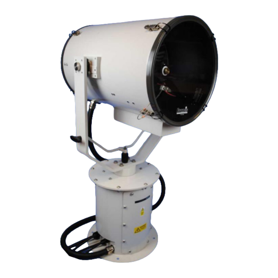
User Instruction & Installation Manual
FX380 Remote Control
2 Kilowatt Xenon Searchlight
Product Reference Number:
A7164 – Variable Speed Motor Unit 240v
A7163 – Variable Speed Motor Unit 115v
Manufacturer's details:
Francis Searchlights Ltd
Union Road, Bolton
Lancashire, BL2 2HJ, UK
Tel:
+44 (0) 1204 558960
Fax:
+44 (0) 1204 558979
http://www.francis.co.uk
E-mail: sales@francis.co.uk
Manual Part Number: C27403
2.11.17
Issue: 2
Distributor details:
Advertisement
Table of Contents

Subscribe to Our Youtube Channel
Related Manuals for Francis Searchlights A7164


Summary of Contents for Francis Searchlights A7164
- Page 1 User Instruction & Installation Manual FX380 Remote Control 2 Kilowatt Xenon Searchlight Product Reference Number: A7164 – Variable Speed Motor Unit 240v A7163 – Variable Speed Motor Unit 115v Manufacturer’s details: Distributor details: Francis Searchlights Ltd Union Road, Bolton Lancashire, BL2 2HJ, UK...
-
Page 2: Table Of Contents
CONTENTS - Introduction - Safety Precautions - Technical Information - Unpacking and Installation Instructions - Electrical Installation - Operating Instructions - Fault Finding - Maintenance and Servicing - Wiring Diagram & General Assembly - Spare Parts List... -
Page 3: Introduction
For your future reference please keep this manual in a safe place. Thank you for specifying a product from the Francis Searchlights range. All Francis products are designed to give complete customer satisfaction and are manufactured to the highest engineering standards in order to ensure optimum performance and service life. -
Page 4: Safety Precautions
2 - Safety Precautions The following instructions must be adhered to, in order to ensure a safe working environment and the safety of the user. Note: When unpacking or manoeuvring the searchlight into its fixing position, suitable lifting points must be used in order to prevent damage to the equipment or personal injury. -
Page 5: Technical Information
3 - Technical Information This product has been designed to operate in accordance with the product specification. The FX380RC 2000 watt searchlight has the following features: All marine grade materials and fixings; Electronic power supply unit; Parabolic aluminium reflector, electro-formed nickel rhodium plated; ... - Page 6 Power Supply Details (Model 8502) General Description Output Power 1400-2200 watts Voltage 22-30 volts D.C. Current 50-85 amperes D.C. Ripple 5% peak-to-peak Input Current 25/22 amperes maximum 40 amperes maximum Voltage 208/237 VAC 110/120 VAC Phase Single Frequency 60 Hz (50Hz available) Output Adjustments 9 steps Size...
- Page 7 Caution Do not allow anything to be placed upon the power supply case; the perforated top is for ventilation and must not be obstructed. Try to select a location as close to the lamp house as practical. Many users install the power supply adjacent to the searchlight where space is available and local codes permit.
- Page 8 Warning The power supplies have two sources of power. Disconnect (turn off) primary power before making adjustments or service procedures. Output power adjustment Warning The power supply stores energy after primary power is switched off. Wait a minimum of two minutes for the capacitor charge to bleed off. Taps are provided on TB1 to alter the output of the power supply.
- Page 9 Xenon lamp power supplies have two stages of operation: Before igniting the bulb – At this time, the voltage at the power supply output terminals reaches “open circuit” value (110 VDC or greater). After igniting the bulb – At this time, the voltage at the power supply output is determined by the load placed on the power supply by the xenon lamp (18-30 VDC).
- Page 10 result in overheating of R3. You may use a clamp-on A.C. ammeter on the common D.C. line to the capacitor bank as an indirect method of checking ripple. The 8502 capacitor bank will have a nominal 25 ampere (AC) current flow. Higher current indicates a high ripple condition. Lower currents, may indicate open or deteriorated capacitors.
- Page 13 Back To Top...
-
Page 14: Unpacking And Installation Instructions
4 - Unpacking and Installation Instructions The following instructions should be read and fully understood prior to installing the equipment to ensure that the correct procedures are followed, and all safety precautions are observed. Note: If the equipment has been in storage for a considerable amount of time, it is advisable to conduct a routine maintenance check on all parts before installation. -
Page 15: Electrical Installation
5 - Electrical Installation Note: ~ When the main power is first applied to the searchlight, the searchlight will carry out a self-test, it will Pan to the left limit and Tilt down to the limit, once this is complete, the searchlight will then move to the centre and horizontal, during this please do not try and operate the searchlight while this test is being carried out. - Page 16 Installation Guidelines A typical installation and connection routine for the FX380RC searchlight is as follows: Referring to wiring diagram C27401 a supply is fed to the junction box, which then provides a common feed to the motor gearbox, searchlight, power supply unit and joystick panel. The searchlight has been pre-wired with 3 meters of cable from the motor gearbox to junction box provided.
- Page 17 Fitting instructions for the 2Kw xenon lamp Referring to the diagram overleaf: Unfasten eight latches (A) on the front and rear of the searchlight. Remove the front bezel (B) and rear bezel (C) assemblies. Unscrew the two M6 hexagon screws (D) from the front lampholder mounting block (E) and remove the front lampholder assembly from the mounting bracket.
- Page 18 Back To Top...
-
Page 19: Operating Instructions
6 - Operating Instructions This equipment is designed for use out of doors, in free air. Never place anything on or cover the searchlight when in use as this may present a hazard. The searchlight can be remotely positioned via the joystick control panel, with the facility for movement up, down, left and right. - Page 20 Setting to Work Safe service in use necessitates the strict observance of the following precautions. Any article fabricated from quartz or glass is inherently fragile and care should therefore be taken, at all times, when handling lamps; Eye protection must be worn when handling lamps that have been removed from their packaging materials.
- Page 21 Notes: 1) XBO lamps are designed for dc operation only. The dc current may only be varied within the limits of the current control range. A XBO lamp operates best at rated current; over the life of the lamp, the current may be increased to its maximum value to compensate for loss of light.
- Page 22 FBUS SPEED CONTROL ASSEMBLY DETAILS MAINS CONNECTORS Live. Neutral Earth TILT CONNECTOR Tilt Motor Red Wire (+) Tilt Motor Black Wire (-) Tilt Encoder Red Wire (5V). (Voyager Brown Wire) Tilt Encoder Green Wire (Phase A Output) (Voyager Yellow Wire) Tilt Encoder White Wire (Phase B Output) Tilt Encoder Black Wire (Voyager Blue Wire) Tilt Limit Switch Common Black Wire...
- Page 23 FBUS Speed Control Board...
- Page 24 CONNECTIONS TO FBUS JOYSTICK CONTROL PANEL FBUS CONNECTOR OV Supply Input Line Terminate (Connect to + for terminate) FBUS + RS485 Data In/Out FBUS - RS485 Data In/Out +24V Supply Input JOYSTICK CONNECTOR Joystick Black Wire Joystick Yellow Wire Joystick Blue Wire Joystick Red Wire FBUS JOYSTICK CONTROL BOARD...
- Page 25 FBUS ADDRESS SWITCHES OVERVIEW FBUS uses two types of address switch. One type is rotary, and the value selected is the value shown on the dial. The other type is rows of switches whose operation is described below: - The switches all operate in the same manner producing a binary value with the highest binary value to the left and the lowest value to the right.
- Page 26 EXAMPLES Standard control panel – panel address set to 5 Switch 1 = Off Switch 2 = On (Value 4 added to address) Switch 3 = Off Switch 4 = On (Value 1 added to address) 4 + 1 = 5 Speed control card - lamp address set to 11 Switch 4 = Off Switch 5 = On (Value 8 added to address)
- Page 27 FBUS DATA PROTOCOL OVERVIEW The Francis bus (FBUS) is a custom communication protocol based on RS485 two wire bi directional communication hardware. The system provides a simple bi-directional link between lamps and lamp control panels. The system allows given panels to communicate with different lamps and also allows a number of panels to communicate with the same lamp.
- Page 28 PANEL TRANSMITTED DATA Panels only send data when there is data to be sent i.e. there has been activity at the panel which must be sent to a given lamp. If there is no data to be sent, a panel will not transmit. The amount of data a panel sends will depend upon the amount of activity at the panel and can be 2 to 10 bytes.
- Page 29 DATA_FOCUS_BUTTON (Hex 0B) This is a single byte command. When the lamp receives this, it will run the focus motor as long as the command remains. A panel will send this command so long as the focus button is pressed. DATA_HOME_BUTTON (Hex 0C) This is s single byte command.
- Page 30 DATA_TILT_POSITION (Hex 19) This is a three-byte command. Following the DATA_TILT_POSITION command two data bytes specify the position to which the lamp must move. The bearing resolution is 0.1 degrees. The value is sent LSB first with the first byte representing the lower position command bits. The MSB (sent last) lower 4 bits represents the remaining value.
- Page 31 The CRC is a simple data checking system. Basically, this is just the sum of the lamps address and bytes above. The value is radix to 8 bits. If the lamp address was 0 (bus address value 16) and the pan and tilt were both at centre and the lamp was switched on and all other status bits were 0 the values would be Hex 110, 80, 80, 01.
- Page 32 4. Send pan value half speed = 128 + (64/2) = Hex A0 within 1mS. 5. Send CRC value, in this case Hex 116 + Hex 01 + Hex A0 = 1D7 after radix to 8 bits = B7. 6. This completes the transmission RECEIVING FROM A LAMP Lamps broadcast data sequentially.
- Page 33 1. Pan Limit. – Either of the pan limit switches operated. Note that this may not actually be a fault. The LED will flash when a limit switch is operated under normal circumstances i.e. the lamp is at the limit of travel.
- Page 34 FBUS INTERFACE UNIT (if supplied) OVERVIEW Francis Searchlights FBUS system is designed to allow multiple control panels to manage a number of searchlights on a common data cable. The data system is application specific and, as such, has a fixed data rate and complex timing.
- Page 35 currently selected lamp is responding the bottom line of the display will show the current pan and tilt angles. SET PANEL ADDRESS The FBUS interface looks like a standard control panel to the FBUS as such it must have a panel address. The panel address must not be set to the same value as any other panel on the system.
- Page 36 FOCUS This function is not implemented on all searchlights. Focus displays the current focus position with a value of 0-100. A value of 50 should represent the most focused beam with the beam diverging above and below 50. Note that the value will ascend from 0-100 the reset back to 0. Pressing the arrow up button will operate the focus motor.
- Page 37 DATA_MOVE_TO_HOME (0x0C) This is a four-byte command (Sync, Lamp address, command, CRC). A lamp receiving this will automatically move to the pre-set home position. The command does not need to be maintained while the lamp moves to home. If a home position has not been defined the home position will be straight ahead with the lamp horizontal.
- Page 38 DATA_MOVE_TO_TILT_POSITION (0x19) This is a six-byte command (Sync, Lamp address, command, position LSB, Position MSB, CRC). The position value is 12 bits and gives a resolution of 0.1 degrees. The most significant byte (sent last) comprises the top 5 bits. The most significant bit (bit 4 –...
- Page 39 8. Focus position - Value between 0 and 100 - finest focus at value 50. 9. Fault Status 1 Bit 0 - Pan motor current high. Bit 1 - Tilt motor current high. Bit 2 - Focus motor current high. Bit 3 - FBUS +24V out current high.
-
Page 40: Fault Finding
7- Fault Finding All fault finding must be conducted by a competent person or qualified Electrical Engineer. Please refer to the following table for the trouble-shooting of Xenon lamps. Fault Cause Remedy Wrong Polarity Lamp incorrectly fitted Anode (large electrode) ... - Page 41 Failure of Lamp to Ignite In the event of the xenon lamp failing to light the following steps should be taken: 1) Check that the mains supply is connected to the input of the PSU. On operating the lamp switch, if the lamp does not light, switch off mains supply and check all fuses; 2) On pressing the lamp switch the lamp still does not ignite, check the searchlight head.
-
Page 42: Maintenance And Servicing
8 - Maintenance and Servicing In order to prolong the service life and performance of your searchlight, the following maintenance guidelines are recommended: Maintenance checks should be conducted before every voyage or at least every three months; Before checking, disconnect the equipment from the supply; ... -
Page 43: Wiring Diagram & General Assembly
240v 2Kw Xenon RC Wiring Diagram Variable Speed C27404 115v 2Kw Xenon RC Wiring Diagram Variable Speed C27402 380v 2 Phase 2Kw Xenon RC Wiring Diagram Variable Speed A7164 / A7163 FX380RC 2Kw variable speed G.A. C27312 Joystick Panel Assembly C26736... -
Page 50: Spare Parts List
Joystick Controller PCB In order to prolong the life and performance of your product, we recommend that you only specify Francis Searchlights spare parts. This will ensure that any warranties on your equipment will not be invalidated. When ordering spare parts please contact the Sales Department at Francis Searchlights Limited.
Need help?
Do you have a question about the A7164 and is the answer not in the manual?
Questions and answers