Advertisement
Set the Timer
Do not rotate the dial anti-clockwise as this will damage the mechanism.
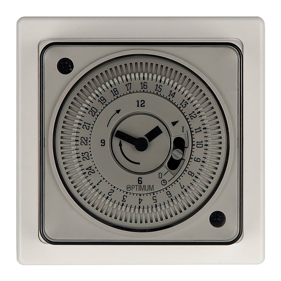
Rotate the minute hand clockwise until the arrowhead on the clock face aligns with the correct time on the outer dial—see Fig. 1.
The dial shows the 24 hour clock. Note that 9 = 9:00 a.m., 21 = 9:00 p.m. When setting-up the 7 day version, align correct time on outer dial, within current day sector of dial. Please note: on the SBSW seven-day timer, the weekdays are printed around the edge of the dial in abbreviations of three languages.
To set ON / OFF times, move all tappets between
 Figure 1.
ON and OFF times required to the outer edge of the dial. See Fig. 1.— to set ON at 7:30 a.m. and OFF at 10:30 a.m. move all tappets to outer position between 07:30 and 10:30 on the dial. Set any other ON/OFF times in a similar manner.
Manual Override
There is a three-position manual selector built-in to the clock dial face. See Fig. 2.

Figure 2.
Position 1 'I' = ON
Position 2 ![]() = AUTO
= AUTO
Position 3 '0' = OFF
The timer incorporates a changeover switch. See Fig. 3. Therefore, when in use as a general purpose timer, the manual switch functions as follows:
In position 1, terminal 2 output is ON
In position 2, the output will switch between terminals 1 & 2, as determined by tappet positions.
In position 3, terminal 1 output is ON.

Installation guide
Installation must be carried out in accordance with the current edition of the I.E.E. Wiring Regulations. It is recommended that installation is undertaken only by a qualified electrician.
Installation Procedure
Switch off supply to socket box.
Unscrew two screws (A) which secure housing and timeswitch to backplate - please see Fig. 4. assembly diagram.
Remove cover and gently pull module from backplate. Do not put undue stress on, or interfere with fixed blue wires.
Fix backplate to socket box.
Connect wiring in accordance with wiring diagram. Do not combine solid and stranded conductors in the same terminal. When connecting stranded conductors use the ferrules provided. Screw terminal recommended torque 0.75Nm.
Fit cover over module and reassemble to backplate. Ensure fixed blue wires are stowed neatly without being trapped.
Re-fit and tighten two screws (A) Switch on mains.

Figure 4.
Wiring diagram - mains switching. The link between 3 and 5 must be fitted by the installer

Wiring diagram - volt free switching. The diagram above shows wiring for a potential-free load.
For low voltage switching connect 230v L & N to 5 & 4 respectively, and switch circuit to 3 & 2.

Specification
Motor: 220-240V AC 50Hz
Temperature rating T55
Switch type: changeover
Rating: 16A resistive / 8A inductive
Not suitable for direct switching of lighting types: Fluorescent, HID, SON, LED
Use a contactor for discharge lamps
Suitable for fitting to surface or flush mounted socket box. For fixed wiring only.
Class II control / Protection class IP20
Complies with European Norm
EN 60730-1: 2011

Automatic Electrical Controls for Household and similar use, and European Directives: LVD; EMC; RoHS

www.tfc-group.co.uk

TFC Group LLP Tonbridge TN9 1TB

Documents / Resources
References
Download manual
Here you can download full pdf version of manual, it may contain additional safety instructions, warranty information, FCC rules, etc.
Advertisement


Need help?
Do you have a question about the OP-SBSW and is the answer not in the manual?
Questions and answers