Advertisement
User instructions
- Set the timer
- Setting a program
- Check program settings
- Manual override
- Installation instructions
- Wiring diagram
- Specification
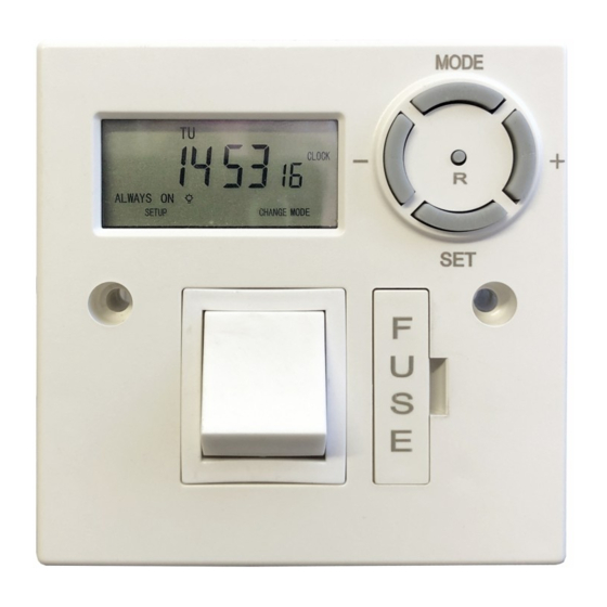
Set the Timer

- Press the R button to reset the timer to its default setting. Activate using a pencil or similar instrument. (pressing R will delete all stored programs)
- Press the Set button to enter function setup. (Note, if another button is not pressed within 10 seconds the display will revert to the normal screen.)
- Use the + or - button to scroll to the clock icon(flashing) and press Set to enter the current time setting mode (hours flashing).
- If you keep the + or - buttons pressed for more than 3 seconds, the display will enter fast scroll mode.
- Use the + or - button to adjust the hours and press Set to confirm, minutes will flash.
- Use the + or - button to adjust the minutes and press Set to confirm. Day will flash.
- Use the + or - button to adjust the day, and press Mode to exit.
Setting a program
- There are 24 ON/OFF programs available.
- Press the Set button twice to enter the programming setting mode.
- Default is program 01 ON, this can be changed if required by pressing + or - button to scroll through the 24 ON/OFF programs as required, pressing the Set button will confirm the program.
- Press the Set button to confirm program 01 ON,hours will flash.
- Use the + or - button to adjust the hours andpress Set to confirm, minutes will flash.
- Use the + or - button to adjust the minutes andpress Set to confirm, days will flash.
- Apart from individual days of the week, the following day combinations of multiple day blocks can be selected by pressing the + or - buttons.
- Monday to Sunday
- Monday to Friday
- Saturday to Sunday
- Monday to Saturday
- Monday + Wednesday + Friday
- Tuesday + Thursday + Saturday
- Monday + Tuesday + Wednesday
- Thursday + Friday + Saturday
- Select day or day block as required and pressthe Set button to confirm.
- Press the + button, this will select the program 01 OFF, press Set to confirm.
- Follow 4 to 7 above to set the 01 OFF program (day or day block must be the same as program ON)
- If no more programs are required, press theMode button to exit.
- If more programs are required follow 3.
- To cancel a program once set, press and holdthe Mode button when the desired program number is flashing i.e. to cancel program 01, press the Set button twice and hold the Mode button down for more than 3 seconds to delete. Pressing the + button again will select 01 OFF.
- Repeat 13 to delete 01 OFF.
This procedure can be repeated to delete any of the 24 programs.
Check program settings
- Press Set button twice to enter program mode.
- Press the + or buttons to scroll through the 24 ON/
OFF programs to check settings. - Press the Mode button to exit and revert to clock mode.
Manual override
When in normal clock mode, pressing the Mode button will scroll through the following switching options.
 ALWAYS ON - timer is permanently ON
PROG - timer is in program mode ON
 PROG - timer is in program mode OFF
ALWAYS OFF - timer is permanently OFF
Installation instructions
Please read these instructions fully before commencing work. The OP-DFST must be installed by a qualified person, in accordance with best practise and current IEE wiring regulations. Do not install the timer onto a flammable surface, or keep stored materials too close. The installed timer should have clearance of at least 150mm in all directions.
Ensure the supply is switched off. In addition, re- move any fuse protection or turn off the circuit break- er. The OP-DFST is designed to be installed onto a flush or surface-mounted electrical back-box of mini- mum 16mm depth. A BS1362 13 Amp cartridge fuse is pre-installed as circuit protection for the radial, or spur connection.
Make sure that the total load on the circuit - with the additional < 13A load connected to the fused spur timer - does not exceed the capacity of the circuit cable, fuse or circuit breaker.
Installation
Connect the incoming supply, and the outgoing load with the wiring diagram (Figure 1.). Use the earth continuity terminal which will be provided in a metal patress box, or the supplied screw terminal connector if using a moulded surface mounted box. Bare earth conductors must be sleeved. A flexible cable outlet, with cable restraint is provided. If the flexible cable outlet is required, remove the blanking cover and route the flexible load cable via the cable re- straint and the outlet hole. Check that all conductors are correctly connected, and terminals are fully tight- ened.
Secure the connected timer to the back-box with the 25mm machine screws provided. Make sure that cables are carefully routed and stowed to avoid pinching, stress or damage.
Wiring diagram

Figure 1.
Specification
Supply: 220-240V AC 50Hz
Temperature rating T45 Fuse: BS1362, 13A Isolation: double pole switch
Switch type: mains, normally open
Rating: 13A resistive / 8A inductive
Not suitable for direct switching of lighting types: HID, SON, LED—use a contactor Class II control / Protection class IP20
Complies with European Norm EN 60730-1: 2011Automatic Electrical Controls for Household and similar use, and European Directives: LVD; EMC; RoHS


www.tfc-group.co.uk
TFC Group LLP Tonbridge TN9 1TB

Documents / Resources
References
Download manual
Here you can download full pdf version of manual, it may contain additional safety instructions, warranty information, FCC rules, etc.
Download Optimum OP-DFST - Digital Fused Spur Timer User Instructions
Advertisement


Need help?
Do you have a question about the OP-DFST and is the answer not in the manual?
Questions and answers