Apeks WTX series - Diving Instrument Installation Manual
- Owner's manual (35 pages) ,
- Installation instructions (2 pages)
Advertisement
INTRODUCTION
CONTENTS: Two 80 inch sections of retractor tubing.
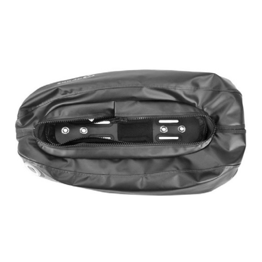
The WTX retractor kit (PN 388300) is an optional retraction system that may be added to the WTX-D30 and WTX-D40 to streamline the buoyancy cell while diving (use of this retractor system is optional) (Fig. 1).
The retractor system is secured through a series of internal loops sewn into the outer bag. The outer retractor (80 in.) runs through the outer loops, through the grommet holes on the rear of the outer bag, where they are tied off and secured. The inner retractor (80 in.) zig-zags through the inner loops, where it is tied off and secured on both sides. The following instructions will guide you through the optimal method of securing the internal retractor system for maximum effect. Please note other methods of configuring the internal retractor system may be done according to preference.
 NOTE: WTX-D18 buoyancy cell cannot accommodate the retractor kit as there are no sewn in loops attached to the outer bag.
OVERVIEW

Fig. 1
INSTALLATION INSTRUCTIONS
- Lay the WTX-D buoyancy cell on a flat surface to install the retractor kit. Remove the inflator from the buoyancy cell by unscrewing the collar at the base of the elbow assembly (Fig. 2).

Fig. 2
Unzip the outer bag, push the bladder connector through and remove the bladder. Leave the bladder attached to the flat valve on the lower left side (Fig. 3).

Fig. 3
This will allow easier access to the outer sewn in loops while installing the retractor kit. - Insert one end of the retractor into the grommet hole located on the bottom of the outer bag (Fig. 4).

Fig. 4
Weave the retractor through the outer loops and out the grommet hole on the opposite side (Fig. 5).

Fig. 5
![warning]() NOTE: Make sure the outer retractor is routed over the bladder when inserting and exiting the grommet holes, this will streamline the bladder at the bottom.Place the bladder back into the outer bag and align the oval cut out in bladder around the plastic plate in the center (Fig. 6).
NOTE: Make sure the outer retractor is routed over the bladder when inserting and exiting the grommet holes, this will streamline the bladder at the bottom.Place the bladder back into the outer bag and align the oval cut out in bladder around the plastic plate in the center (Fig. 6). 
Fig. 6
Ensure the bladder connector is inserted through connector hole in outer bag (Fig. 7).

Fig. 7- There are two sets of inner loops, upper and lower. Insert one end of the retractor into the lower loop, closest to the grommet hole on the bottom of the outer bag (Fig. 8).

Fig. 8
Weave the retractor in a zig zag pattern through the loops around the diameter of the outer bag (Fig. 9).

Fig. 9
After exiting the last loop on the opposite side, pull the retractor tight until you see the outer bag starting to compress. Tie an overhand knot to hold the inner retractor in place. Repeat process for other side (Fig. 10).

Fig. 10 - Place one hand over the grommet hole and grasp the retractor with the other hand (Fig. 11).

Fig. 11
Pull the retractor tight until you see the outer bag starting to compress. Tie a double overhand knot in the retractor directly below the grommet hole (Fig. 12).

Fig. 12
Repeat process for other side. Do not trim the excess of the retractors at this time as adjustment in the tension might still be needed. - Attach the inflator to the buoyancy cell by screwing the collar at the base of the elbow to the bladder connector (Fig. 13).

Fig. 13
Close the zipper on the outer bag (Fig. 14).

Fig. 14 - Inflate and deflate the buoyancy cell several times to allow the retractors to work into place. Ensure the proper tension of the retractor system has been achieved (Figs 15 & 16).

Fig. 15

Fig. 16 - Orally inflate the buoyancy cell to be sure the retractors are not too tight (Fig. 17).

Fig. 17
You should be able to inflate the buoyancy cell with little effort. If you cannot orally inflate the buoyancy cell, re-adjust the tension of the retractor system. Once the buoyancy cell has been inflation tested and the desired tension has been achieved, the excess of the retractors can be trimmed below the overhand knot.


Assembly of the WTX retractor kit to the WTX-D buoyancy cell is now complete.
If you have any questions regarding the information found in this manual, please contact your regional Apeks Dealer or Distributor. Distributor information is available on the Apeks website at: www.apeks.co.uk

Documents / Resources
References
Download manual
Here you can download full pdf version of manual, it may contain additional safety instructions, warranty information, FCC rules, etc.
Download Apeks WTX series - Diving Instrument Installation Manual
Advertisement


Need help?
Do you have a question about the WTX Series and is the answer not in the manual?
Questions and answers