
Related Manuals for Longrun LRF-2000M


Summary of Contents for Longrun LRF-2000M
- Page 1 Ultrasonic Flow Meter User Manual Type: LRF-2000M LONGRUN INDUSTRIAL INSTRUMENT CO.,LTD...
-
Page 2: Table Of Contents
Contents 1. Must-knows about LRF-2000M ..................4 2. Introduction to new generation LRF-2000M ..............5 2.1 Development introduction ..................5 2.2 Features ......................6 3. On Board Segmental LCD display Details ............... 8 4. Menu Window Details ....................12 5. - Page 3 www.ultrasonicscn.com 6.17 How to produce an alarm signal ................ 34 6.18 How to use the built-in Buzzer ................35 6.19 How to use the OCT output ................35 6.20 How to modify the built-in calendar ..............35 6.21 How to view the Date Totalizers ................ 35 6.22 How to use the Working Timer................
-
Page 4: Must-Knows About Lrf-2000M
Please read the following paragraphs when you use LRF-2000M for the first time The setup of a LRF-2000M ultrasonic flow converter needs one of the three tools. The first tool is a parallel LCD and keypad module which can be connected to the 20 Pins port. -
Page 5: Introduction To New Generation Lrf-2000M
2. Introduction to new generation LRF-2000M 2.1 Development introduction The new generation LRF-2000M is developed with the experience of 12 years of manufacturing and based on our version-7 and version-11 flow meters. By using the high performance MSP430FG4618 microprocessor made by Taxes Instruments, it is intend to provide our customers with lower cost but of high performance general purpose ultrasonic flow meter/heat meter/ultrasonic flow converter. -
Page 6: Features
www.ultrasonicscn.com The transducers can be one of any kinds of the types made by this company, include the clamp-on type, the insertion type, the PI- type and standard-pipe type. It can even use transducers made by the users or the transducers made by other company. The module will satisfy the measurement requirement for most kind of liquids, such as water, sea water, sew water and chemistry liquids. - Page 7 www.ultrasonicscn.com 14. 32 records of power-on and power-off data. Data can be read through MODBUS. 15. Built-in data logger/printer, full programmable with what to be print, the start time, interval, and output times. 16. Programmable pulse width of OCT output. 17 One Parallel Interface for display and keypad.
-
Page 8: On Board Segmental Lcd Display Details
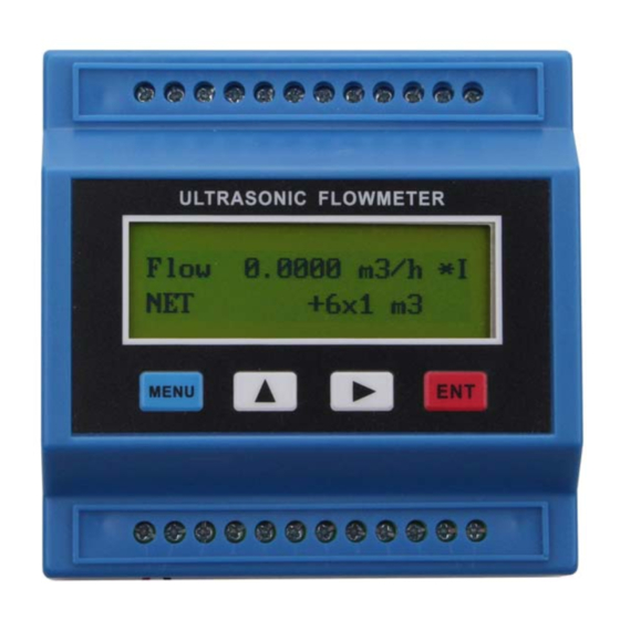
OCT outputs, which is related to MENU79, the RELAY output setup’ 3. On Board Segmental LCD display Details Each LRF-2000M has an on board 96 segments LCD display, like in the figure. It is only for the purpose of displaying. There 40 displays in total. - Page 9 www.ultrasonicscn.com Repair needed Direction of the flow No flowing or flow not above threshold Battery is full For flow rate For energy flow rate For Total Energy The temperature difference By the default setting (0 or 1 is input to [M3.]), when the only key is press shortly, the on-board display will go to the next display, for example, from display 02 to display 03.
- Page 10 www.ultrasonicscn.com Temperature 34.2345 Temperature difference △ ℃ 000012.14 /h Failure Timer Unit : hours 80 9 States Error Code, Signal Strength, and Quality 23.15.49 Calendar, Time 07-12-31 Calendar, date E0 0.1234 Flow velocity Unit: m/s E1 99.876 Travel time rate %, between the measured and calculated travel time E2 1480.3...
- Page 11 www.ultrasonicscn.com 0.0023 M-clock Should always <0.1 C3 12.435 Current input at AI3 Unit: mA C4 0.0001 Current input AI4 Unit: mA C5 0.0000 Current input AI5 Unit: mA 0000234.5 KWh Negative Total Heat 000045.67 m3 Net total flow Decimal unit is determined by 000012.34 m3 Negative total flow Decimal unit is determined by...
-
Page 12: Menu Window Details
www.ultrasonicscn.com “9” clock or calendar error(s) “A” Parameter checksum error “b” Software checksum error “C” Temperature circuits error “d” Reserved “E” Internal timer over flow “F” Analog Inputs over range error If more than one error code exists by the same time, the error codes will be display one after another with time seconds. - Page 13 www.ultrasonicscn.com Display flow rate and NEG(negative) totalizer If the negative totalizer is turned off, the negative totalizer value shown on the screen is the value prior to its turn off Display date and time, flow rate. The date and time setting method is found in MENU60 Display energy rate(instantaneous Caloric)and total energy (Caloric) Display temperatures, inlet T1, outlet T2...
- Page 14 www.ultrasonicscn.com (6) Propane at -45C (7) Butane at 0C (8)Other liquids(need to enter sound speed in M21 and viscosity in M22) Diesel Oil (10)Caster Oil (11)Peanut Oil (12) #90 Gasoline (13) #93 Gasoline (14) Alcohol (15) Hot water at 125C Window for entering the sound speed of non- standard liquid, used only when option item 8 ‘Other’...
- Page 15 www.ultrasonicscn.com (2) Function to store the current parameters into the flash memory, so that these parameters will be solidified and will be loaded as the default parameters every time when power is turned on. Entry to store to or restore from the internal Flash memory, as many as 9 different pipe parameter configurations To save or load the current setup parameter, use the going up or going down keys to change the address number, press ‘ENT’...
- Page 16 www.ultrasonicscn.com stop the manual totalizer. Interface Language selection. The selection could also be changed automatically by the system, if English LCD display is used as the display device. Setup for local segmental LCD display. Enter 0 or 1 for the non-auto-scan mode; Enter 2~39 for the auto-scan mode.
- Page 17 www.ultrasonicscn.com Select analog output (4-20mA current loop, or CL) mode. Available options: (0) 4-20mA output mode (setup the output range from 4-20mA) (1) 0-20mA output mode (setup the output range from 4-20mA, This mode can only be used with Version-15 flow meter) (2) Serial port controls 0-20mA (3) 4-20mA corresponding fluid sound speed (4) 20-4-20mA mode...
- Page 18 www.ultrasonicscn.com function. Please remember to order the module if you need frequency output function. For Version-15 flow meter, you need to indicate on your orders that you need the frequency function; Otherwise you will get a flow meter which has no frequency output circuits.
- Page 19 www.ultrasonicscn.com 14.Energy NET Pulse 15.MediaVel=>Thresh 16.MediaVelo<Thresh 17.ON/OFF viaRS232 18. Daily Timer (M51) 19.Timed alarm #1 20. Timed alarm #2 21.Batch Totalizer Full 22. Periodically M51 Timer 23. Oct Not Using The OCT circuit does not source voltage at its output. It must be connected with an external power and pull-up resistant for some occasions.
- Page 20 www.ultrasonicscn.com By selecting item #9, the batch totalizer could act as totalizer witch runs for only a period of the day so that a alarm signal could be produced if the total flow during that time period is over a certain amount of. For example, if you want a alarm signal which stand for the total flow is over 100 cubic meters during the period of every day from 20:00 to 06:00, setups is like M51 start time =20:00:00...
- Page 21 www.ultrasonicscn.com signal strength will be, and more reliable readings will be made. Q value is presented by 00 to 99, the bigger the better. It should at least be great than 50 for normal operations. Displays the Time Ratio between the Measured Total Transit Time and the Calculated time.
-
Page 22: Begin To Mount And Measure
www.ultrasonicscn.com Whenever the estimated sound speed (displayed in M92) exceeds this threshold, an alarms signal will be generated and can transmitted to BUZZER or OCT or RELAY. This function can used to produce an alarm or output when fluid material changes. Displays total flow for this month(only for the time past) Displays total flow for this year(only for the time past) Display the not-working total time in seconds. - Page 23 www.ultrasonicscn.com The following parameters need to be configured for a proper measurement: (1) Pipe outer diameter (2) Pipe wall thickness (3) Pipe materials (for non-standard pipe materials*, the sound speed for the material must be configured too) *Standard pipe materials and standard liquids refer to those with the sound parameters that have already been programmed into software of the flow meter, therefore there is no need to configure them (4) Liner material and its sound speed and thickness, if there is any liner.
-
Page 24: Transducers Mounting Allocation
www.ultrasonicscn.com (13) Press MENU 8 to check up the working status, “R” means work well (14) Press MENU 1 to check up the measuring data. Note: 1. For heat measurement, please connect PT100 which installed in water supply and water back pipe to T1, TX1, T2, TX2, GND terminal. 2. -
Page 25: Transducers Installation
www.ultrasonicscn.com Examples of optimum locations. Principles to selection of an optimum location (1) Install the transducers on a longer length of the straight pipe. The longer the better, and make sure that the pipe is completely full of liquid. (2) Make sure that the temperature on the location does not exceed the range for the transducers. -
Page 26: Wiring Diagram Of Transducer
www.ultrasonicscn.com 5.3.1 Wiring diagram of transducer 5.3.2 Transducers Spacing The spacing value shown on menu window M25 refers to the distance of inner spacing between the two transducers. The actual transducers spacing should be as close as possible to the spacing value. 5.3.3 V-method Installation V-method installation is the most widely mode for daily measurement with pipe inner diameters ranging from 15 mm to 200 mm. -
Page 27: Z-Method Installation
www.ultrasonicscn.com 5.3.4 Z-method Installation Z-method is commonly used when the pipe diameter is above 200mm. 5.3.5 W-method Installation W-method is usually used on pipes with a diameter from 15mm to 50mm. 5.3.6 N-method Installation Rarely used method. -
Page 28: Installation Checkup
www.ultrasonicscn.com 5.4 Installation Checkup Through the checkup of the installation, one can: check the receiving signal strength, the signal quality Q value, the traveling time difference of the signals, the estimated liquid speed, the measured traveling time of the signals and the calculated traveling time ratio. Therefore, optimum measurement result and longer running time of the instrument can be achieved. -
Page 29: Time Ratio Between The Measured Total Transit Time And The Calculated Time
www.ultrasonicscn.com 5.4.3 Time Ratio between the Measured Total Transit Time and the Calculated Time This ratio would be used to check the transducer installation. If the pipe parameters are entered correctly and the transducers are installed properly, the value for this ratio should be in the range of 100±3. -
Page 30: How To Judge The Liquid Flowing Direction
www.ultrasonicscn.com 6.2 How to judge the liquid flowing direction (1) Make sure that the instrument works properly (2) Check the flow rate for the indication. If the displayed value is POSITIVE, the direction of the flow will be from the A transducers to the B transducers; if the displayed value is NEGATIVE, the direction will be from the B transducers to the A transducers;... -
Page 31: How To Reset The Totalizers
www.ultrasonicscn.com 6.7 How to reset the totalizers Use M37 to reset the proper totalizer. 6.8 How to restore the flow meter with default setups Use M37, when the ‘selection’ message is displayed. Press the dot key first and the message ‘Master Erase’... -
Page 32: How To Get A Scale Factor For Calibration
www.ultrasonicscn.com function in window M42 will bring a more accurate measurement result. Make sure that there is no liquid running inside the pipe, and then run the function in window M42 by pressing the ENT key. 6.12 How to get a scale factor for calibration A scale factor is the ratio between the ‘actual flow rate’... -
Page 33: How To Use The Frequency Output
www.ultrasonicscn.com Example B: flow rate range is -500-0-1000m /h. If flow direction is not an issue for you, you may select 20-4-20mA mode in M55. Then, enter 500 in M56 and 1000 in M57. If flow direction is an issue, you may select 0-4-20mA mode in M55. This means that the current loop will output 0-4mA when flow rate is negative and 4-20mA when flow rate is positive. -
Page 34: How To Use The Totalizer Pulse Output
www.ultrasonicscn.com 6.16 How to use the Totalizer Pulse Output The totalizer output will produce a pulse output with every unit flow of the totalizer. The totalizer pulse output can only be realized by mapping the pulse output to the OCT or BUZZER hardware devices. -
Page 35: How To Use The Built-In Buzzer
www.ultrasonicscn.com Example C: assume we need the OCT output to activate when flow rate exceeds 100~500m and the relay output to activate when flow rate exceeds 600~1000m3/h. The following setup steps would be recommended: (1) Enter flow rate lower limit 100 in M73 (2) Enter flow rate upper limit 500 in M74 (3) Enter flow rate lower limit 600 in M75 (4) Enter flow rate lower limit 1000 in M76... -
Page 36: How To Use The Working Timer
www.ultrasonicscn.com 6.22 How to use the Working Timer Use the working timer to check the time that has passed with a certain kind of operation. For example, use it as a timer to show how long a fully-charged battery will last. Under M72, press ENT key and then select YES to reset the timer. -
Page 37: How To Output Analogue Voltage Signal
www.ultrasonicscn.com 6.27 How to output analogue voltage signal Parallel a 250 resistance to the terminal of the Current loop output (No.21, 22), then you can change the 4-20mA output to analogue voltage output. 6.28 How to adjust the LCD display You may use menu window 70 to setup the LCD display backlight and menu window 71to adjust contrast it. -
Page 38: How To Solidify The Parameters
www.ultrasonicscn.com We have adjusted every set of meter before delivery. Unless you find the current indicated in menu 58 is different with the actual current output, please do not do this operation. Press keys MENU 0 , use the password ”4213068” to enter the window. Notice: the ▼/- window will close after power off and the password will become invalid then. - Page 39 www.ultrasonicscn.com The menu can realize almost 12 parts linearity correcting. The user can choose from two points to twelve points to execute the linearity correcting according to user actual condition. In order to explain the usage method of the menu, we suppose that we get the following table data through calibration the meter.
-
Page 40: How To Save / Restore Frequently-Used Pipe Parameters
LRF-2000M can also set to automatically output data at a period which is programmable. The LRF-2000M also has a special command sets to facilitate the use of the flow meter in a GSM network. -
Page 41: Modbus Registers Table
LRF-2000M can only support MODBUS functions code 3 and code 6, i.e. reading registers and writing a register. For example, reading the registers from REG0001 to REG0010 in the unit #1 (ultrasonic flow meter) under the MODBUS-RTU format, the command could be as following (hex)... - Page 42 www.ultrasonicscn.com Singular IEEE-754 number, also called FLOAT 0017-0018 Positive energy accumulator LONG 0019-0020 Positive energy decimal fraction REAL4 0021-0022 Negative energy accumulator LONG 0023-0024 Negative energy decimal REAL4 fraction 0025-0026 Net accumulator LONG 0027-0028 Net decimal fraction REAL4 0029-0030 Net energy accumulator LONG 0031-0032 Net energy decimal fraction...
- Page 43 www.ultrasonicscn.com 0061 LCD Back-lit lights for number of INTEGER Writable。In unit seconds second 0062 Times for the beeper INTEGER Writable。Max 255 0062 Pulses left for OCT INTEGER Writable。Max 65535 0072 Error Code 16bits, see note 4 0077-0078 PT100 resistance of inlet REAL4 In unit Ohm 0079-0080...
- Page 44 www.ultrasonicscn.com 0113-0114 Net accumulator REAL4 In Cubic Meter, float 0115-0116 Positive accumulator REAL4 In Cubic Meter, float 0117-0118 Negative accumulator REAL4 In Cubic Meter, float 0119-0120 Net energy accumulator REAL4 In GJ,float 0121-0122 Positive energy accumulator REAL4 In GJ,float 0123-0124 Negative energy accumulator REAL4 In GJ,float...
- Page 45 www.ultrasonicscn.com 0056 0191-0192 Flow rate for Auto-Save REAL4 Time to save by 0056 0221-0222 Inner pipe diameter REAL4 In millimeter 0229-0230 Upstream delay REAL4 In microsecond 0231-0232 Downstream delay REAL4 In microsecond 0233-0234 Calculated travel time REAL4 In microsecond 0257-0288 LCD buffer 0289 LCD buffer pointer...
- Page 46 www.ultrasonicscn.com 1 liter 2 American gallon (GAL) 3 imperial gallon (IGL) 4 American million gallon (MGL) 5 Cubic feet (CF) 6 American oil barrel (1 barrel =42gallon) (OB) 7 Imperial oil barrel (IB) While The energy flow rate =(N+Nf )×10 n-4 (unit decided by REG 1441) n=(0~10) is the energy multiplier which is in REG1440 (2) Other variables are not given here.
-
Page 47: Register Table For The Date Accumulators
www.ultrasonicscn.com Bit10 parameters check-sum error Bit11 ROM check-sum error Bit12 temperature circuits error Bit13 reserved Bit14 internal timer over flow Bit15 analog input over range Please try to override these energy-related bits first when in flow-only measurement, (5) Unit code for flow rate Cubic Cubic meter Cubic meter... - Page 48 www.ultrasonicscn.com before yesterday are in REG2817-2824, and the data for the day of 2 days ago are in REG 3321-3328. REGISTER TABLE for the DAY accumulators Block numbe Register variable format Note 0162 Data pointer Integer Range:0~63 2817 Day and Error Code Day in high byte 2818 Month and year...
-
Page 49: Register For Power-On And Power-Off
www.ultrasonicscn.com 0163 Data pointer for the Integer Range: 0~63 month 3329 Error Code 3330 Month and year Year in high byte 3331-3332 Total working time LONG 3333-3334 Net total flow for the REAL4 month 3335-3336 Net total energy for REAL4 the month 3337 Error Code... - Page 50 www.ultrasonicscn.com 3587 Power-on month and Month in low byte, year in year high 3588 Power-on error code B15 stand for corrected lost flow. 3589 Power-off second and Second in low byte, minute in minute high 3590 Power-off hour and Hour in low byte, day in high 3591 Power-off month and Month in low byte, year in...
-
Page 51: The Fuji Extended Communication Protocol
7.2 The FUJI extended communication protocol LRF-2000M is compatible with the LRF7-FUJI extended communication protocol which used in our previous Version7 ultrasonic flow meters. This protocol is a set of basic commands that are in ASCII format, ending with a carriage return (CR) and line feed (LF), For most of the commands, The line feed (LF) should be better omitted for fast responding. - Page 52 www.ultrasonicscn.com Time@TDS1=(cr) Set date and time yy-mm-dd,hh:mm:ss M@(cr) Send a key value as if a key is M@(cr) note 5 pressed. @ is the key value LCD(cr) Returns current window content LOCK0(cr) Unlock the system Has nothing to do with the original password.
- Page 53 www.ultrasonicscn.com of AI3 AI4(cr) Return temperature /pressure value ±d.ddddddE±dd(cr)(lf) of AI4 AI5(cr) Return temperature /pressure value ±d.ddddddE±dd(cr)(lf) of AI5 ESN(cr) Return the ESN (electronic serial ddddddd(cr)(lf) note 7 number) of the flow meter Prefix of an IDN-addressing-based Note 8 networking, The IDN address is byte, range 0-253 Prefix of an IDN-addressing-based Note 8...
-
Page 54: 1Command Prefixes And The Command Connector
www.ultrasonicscn.com 5.@ stand for key value, for example, value 30H means key ‘0’. The command ‘M4(cr)’ acts just like the number 4 key on the keypad was pressed. 6. ’a’ stands for the output current value. The maximum value should not exceed 20.0 For example AO2.34567, AO0.2 7.... -
Page 55: The Compatible Communication Protocols
Flow meters made by our manufacturer have more than 10 different communications protocols. For the easier replacement of a water meter, most of these protocols are realized in LRF-2000M flow meters. Here only one of them, the default for compatible protocols CRL-61D (D<=50mm), is given for reference. - Page 56 www.ultrasonicscn.com interface:RS232,RS485 baud rate:9600 by default,select other 15 different baud rate by Menu 62 parity:NONE, EVEN, ODD can be chosen from Menu 62 Data bits:8 Stop bits: 1, 2 In the following explanation: XXh stands for the address (or network ID)of the instrument, range:00h-FFh. YYh stands for the new address that will be assigned, range:00h-FFh.
- Page 57 www.ultrasonicscn.com Answer: 26h XXh 49h LL(BCD 码 ) ZZh The difference between the command 4A and command 49 is that the late command reads out the data which are recorded in the meter by the time which is defined by command 4C.
-
Page 58: Key Value Table
www.ultrasonicscn.com 7.4 Key Value Table The key values are used in a network application. By use of the key value and a command ‘M’, we can operate the flow meter through the network on a computer or other kind of terminals. For example, the command ‘M0(cr)’... -
Page 59: Error Code And Counter-Measures
www.ultrasonicscn.com Number errors Initialize the calendar by menu Date Time Error with the calendar window M61 Reboot Hardware Contact the factory repetitively problems 8.2 Error Code and Counter-Measures The LRF-2000S ultrasonic flow meter will show Error Code in the lower right corner with a single letter like I, R etc. -
Page 60: Other Problems And Solutions
(2) Problem with transducer installation. (3) There is a ‘Zero Point’. Try to ‘zero’ the instrument by using M42 and make sure that the flow inside the pipe should be standstill. LONGRUN INDUSTRIAL INSTUMENT CO.,LTD 24 hours service: +86-186-5435-6933 Tel: +86-543-3611555 Fax: +86-543-3615999 E-mail: info@ultrasonicscn.com...
Need help?
Do you have a question about the LRF-2000M and is the answer not in the manual?
Questions and answers