Table of Contents
Advertisement
Quick Links
Advertisement
Table of Contents

Related Manuals for Longrun LRF-3000P


Summary of Contents for Longrun LRF-3000P
- Page 1 - 1 -...
- Page 3 Preface Thanks for purchasing the product! The User’s Manual covers functions, settings, wiring and troubleshooting methods of this flowmeter. Please carefully read this manual before use. After reading the manual, please keep it in a proper place for reference when you operate the flowmeter. Notes Any modifications concerning function update in this manual will not be notified.
-
Page 5: Table Of Contents
LRF-3000P Ultrasonic flowmeter Contents 1.1Product Liabilities and Quality Assurance ............- 3 - 1.2Safety Instructions to Operators ................- 4 - Chapter IIDescriptions of the Flowmeter ................- 5 - 2.1Delivery Scope ......................- 5 - 2.2Measuring Principle ....................- 7 - 2.3Application Scope ...................... - Page 6 LRF-3000P Ultrasonic flowmeter Copyrights and Data Protection Content of this file has been carefully checked. We don’t promise that the content is totally correct and completely identical with the latest version. Content of this file and related products are under protection of China’s copyright laws. Without authorization in...
-
Page 7: Product Liabilities And Quality Assurance
LRF-3000P Ultrasonic flowmeter 1.1 Product Liabilities and Quality Assurance The purchaser should judge by himself whether the flowmeter is applicable or not, and shall bear related responsibilities. The manufacturer would bear no responsibilities for any consequences arising from the purchaser’s misuse of the flowmeter. The purchaser may lose the rights for quality assurance if the flowmeter or the system is installed or operated in a wrong way. -
Page 8: Safety Instructions To Operators
LRF-3000P Ultrasonic flowmeter 1.2 Safety Instructions to Operators Caution! For your safety, please carefully read the following safety instructions before use. With this manual, you could set up correct operating conditions of this flowmeter to ensure safety and efficiency in use. -
Page 9: Chapter Iidescriptions Of The Flowmeter
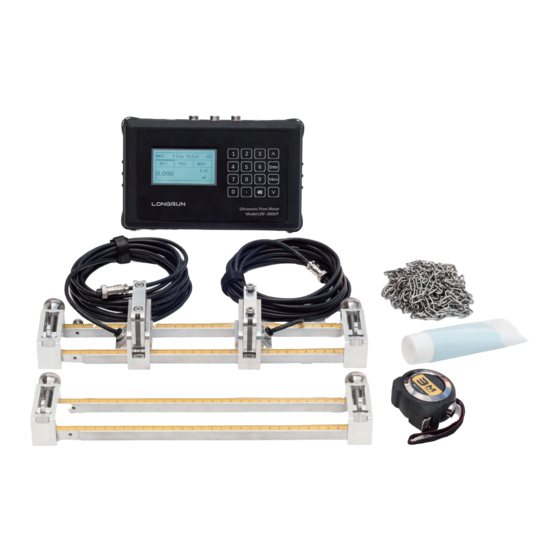
LRF-3000P Ultrasonic flowmeter Chapter II Descriptions of the Flowmeter 2.1 Delivery Scope Prompts! Please carefully check whether the packing case is damaged or loaded/unloaded in an improper way or not. If it is damaged, please notify the delivery man and the manufacturer or the consignor and describe the damage in details. - Page 10 LRF-3000P Ultrasonic flowmeter Structural Configuration of Ultrasonic Flowmeter Accessories 1. Carrying Case*1pc. 2. Transmitter (Electronic)*1pc. 3. Transducer (Sensor) *1 pair. 4. Mounting track *1 set, ST or DT 5. Pipe straps *2 pairs. 6. Coupling compound (Grease)*1 pc, Battery charge*1pc , Output cable*1pc and Tapeline*1...
-
Page 11: Measuring Principle
LRF-3000P Ultrasonic flowmeter 2.2 Measuring Principle This series of ultrasonic flowmeter is an industrial time-difference type ultrasonic flowmeter. It applies the latest industrial-level PFGA 700-thousand- gate-array chip , which extremely improves the signal sampling frequency and bubble tolerance rate; the self-developed TGA technology makes it be capable of dealing with more complex logic and calculation to provide more accurate and faster measurements, and ensures the flowmeter could endure non-continuous bubbles or impurities within 5 sec. -
Page 12: Nameplate
LRF-3000P Ultrasonic flowmeter 2.4 Nameplate Prompts! Please check the nameplate and confirm whether the goods are identical with your order or not. Check whether the power supply on the nameplate is correct or not. The following shows information on the nameplate: Ultrasonic Flowmeter Max. -
Page 13: Connecting Electrical Cables
LRF-3000P Ultrasonic flowmeter 3.3 Connecting electrical cables Warning! Signal cables and power cables must be connected while the power is off. Warning! As specified, the meter must be connected to the protective ground terminal to protect operators from electric shock. -
Page 14: Transmitter Connections
LRF-3000P Ultrasonic flowmeter 3.4 Transmitter Connections 3.4.1. Power supply Please pay special attention to the power supply. Please connect related power supply according to the symbols of connecting terminals. 3.4.2. Transmitter connections Once the flowmeter is installed at the designated place as required, you can start connections. -
Page 15: Chapter Iv Operation Panel And Quick Start
LRF-3000P Ultrasonic flowmeter Chapter IV Operation Panel and Quick Start 4.1 Power on Warning! Please check the meter is correctly installed or not before power on, including: Connecting the power supply as specified; Please check the electrical connection of the supply power is correct or not. - Page 16 LRF-3000P Ultrasonic flowmeter Energy meter display function Note: It is a function of energy meter and only the ultrasound heat meter has this function. Press [Menu] key and digital key [2], i.e.: Menu + 2, to enter M2 heat display interface shown as follows:...
-
Page 17: Keyboard Operation
LRF-3000P Ultrasonic flowmeter 4.3 Keyboard Operation 4.3.1 Descriptions Use digits [0~9] and [ . ] to input digits or menu number. ] key is used for left backspace or deleting the characters on left. ] and [ ] keys are used for entering the previous or next menu; the key is plus or minus when inputting digits. -
Page 18: Chapter V Installation
LRF-3000P Ultrasonic flowmeter Chapter V Installation 5.1 Installation, Storage and Prompts Prompts! Please carefully check whether the packing case is damaged or loaded/unloaded in an improper way or not. If it is damaged, please notify the delivery man and the manufacturer or the consignor and describe the damage in details. -
Page 19: Pipe Design And Selection
LRF-3000P Ultrasonic flowmeter 5.2 Pipe Design and Selection The following should be taken into account when selecting a pipe: 5.2.1 Installation Environment It’s better to install the flowmeter indoors; if you have to install it outdoors, you should take measures to avoid direct sunlight or rainwater. - Page 20 LRF-3000P Ultrasonic flowmeter Caution: DO ensure that the flowmeter is filled. DO NOT make the liquid flow downwards vertically, or it may have bubbles. 5.2.4 Requirements on the front/rear straight pipe sections DO ensure a straight pipe section at least ten times of the pipe diameter (D) in the upstream of the flowmeter and at least five times of the pipe diameter (D) in the downstream of the flowmeter.
- Page 21 LRF-3000P Ultrasonic flowmeter Install after valves Install on diameter-reduced pipe Install on diameter-expanded pipe 5.2.5 Requirements on Transducer Installation Angle When being installed on horizontal pipes, the transducer should be installed at 3 o’clock or 9 o’clock, i.e. on both sides of the pipe. It’ not recommended to install it on top or at bottom of the pipe because it’s easy to cause bubbles at the top and accumulate sands or impurities at the...
-
Page 22: Transducer Installation
LRF-3000P Ultrasonic flowmeter 5.3 Transducer Installation Handling and unpacking It’s better not to unpack it before installing it to designated location to avoid damage. DO NOT heavily throw the flowmeter or press heavily on it, especially the probe surface, or the sealing surface may be damaged. - Page 23 LRF-3000P Ultrasonic flowmeter 5.3.2 Transducer Installation Modes You should choose the way for installation that the client could select a transducer according to the measurement site. Generally, there are two installation methods for transducers: V-shape installation and Z-shape installation. V-shape installation: Two transducers are installed on one side of the pipe, and the sound wave forms a V-shape reflection path on the pipe wall.
- Page 24 LRF-3000P Ultrasonic flowmeter Step 1: Firstly, determine the installation site of the two transducers on the pipe and remove all iron rust, paint stains and dirt. Step 2: Apply enough couplant on the first half (signal generating position) of the transducers and place it on the pipe, press the transducers against the pipe and ensure there are no voids.
- Page 25 LRF-3000P Ultrasonic flowmeter The arrows on transducers must be identical Note: The following shows the with the fluid direction top view of the horizontal pipe section User’s pipe Upstream straight pipe Downstream straight L1>10D pipe L2>5D Installation spacing L (mm)
- Page 26 LRF-3000P Ultrasonic flowmeter Step4. Open the ball vale and insert the transducer into the pipe, and measure the length between the outer side and the handle mark (H), trying to make it conform to the following formula: H = 216 –d1-d2...
- Page 27 LRF-3000P Ultrasonic flowmeter Note: The following shows the top view of the horizontal pipe section Waterproof plug Transducer Lock nut Service position Ball valve of transducer Short pipe on the mounting base Weld the short pipe on the pipe User’s pipe...
-
Page 28: Chapter Vi Operation
LRF-3000P Ultrasonic flowmeter Signal intensity (UP/DN indicates upstream/downstream transducer): LRF series ultrasonic flowmeter applies 00.0-99.0 to indicate corresponding signal intensity, the bigger the value, the stronger the signal intensity. In normal operation, the signal intensity of the upstream/downstream transducer should be >75 as required. If the signal intensity is less than 75, please check whether the transducer is correctly installed or not again, check whether the couplant is applied properly or not;... -
Page 29: Common Functions
LRF-3000P Ultrasonic flowmeter be set accurately. Please carefully read the instructions if necessary. Non-professionals are not allowed to operate the flowmeter. 6.1 Common Functions 6.1.1 How to Judge its Operating Status If it displays "*R", it indicates the flowmeter works normally. - Page 30 LRF-3000P Ultrasonic flowmeter Cut zero point M22 menu-Cut-1. Yes, it displays “success” if zero point is cut. and the flowmeter would return to M01 menu. Reset zero point M22 menu--Reset-1. Yes 6.1.4 Meter Coefficient Meter coefficient indicates the specific value of actual flow and the display value of the flowmeter. For example, the actual flow at the measurement point is 3 and the flowmeter displays 2.99, then the meter coefficient is...
- Page 31 LRF-3000P Ultrasonic flowmeter However, when 0-4-20mA output is used while considering the flow direction, you should consider two different conditions; when the flow direction is reverse, the output current is 0~4mA; when it is forward, the output current is 4~20mA.
- Page 32 LRF-3000P Ultrasonic flowmeter 6.1.10 4-20mA Output Calibration Note: Each flowmeter is strictly calibrated before leaving factory. If you are not sure it is calibrated or not, please try not to use this function. If you are sure that the display value is not identical with the actual output current, you could carry out 4-20mA output calibration.
- Page 33 LRF-3000P Ultrasonic flowmeter File type: Text file (.TXT). Number of files: 512pcs at maximum. The file saved each time should be 120 bytes. If the flowmeter saves data once per 5 sec, the file saved in 24 hours is 120*3600/5*24 = 2073600byte~2.1Mbyte; therefore,1Gbyte SD card could save data for 1024/2.1= 487.6187 days.
-
Page 34: Description Of Operation Menus
LRF-3000P Ultrasonic flowmeter 6.2 Description of Operation Menus 6.2.1Abbreviated codes of menus Identification Flow Indication in Level One Menu Menu Codes and Description M00 flow totalizar M01 flow rate *R- System running normally *E- Signal unknown M02 heat *D- Adjusting gain... - Page 35 LRF-3000P Ultrasonic flowmeter Identification Flow Indication in Level One Menu Menu Codes and Description M37 SD card settings (optional) M40 metric unit M41 flow unit Flow unit options in input/output settings M42 energy unit M43 temperature unit M50 serial number...
-
Page 36: Menu Configuration
LRF-3000P Ultrasonic flowmeter 6.3 Menu Configuration Total Flow Flow Total Display flow NET Total Display flow POS Total 123.4 Display flow NEG Total m³ Press up/down key to switch Flow Rate Flow 0.00 Display transient flow and transient velocity 0.000 NET Total and flow velocity - auto switching and m³/h... - Page 37 LRF-3000P Ultrasonic flowmeter Cool Rate Cool Display cool total 100.2 Transient cool total and temperature - auto switching 123.4 and display (6s) Only display inlet temperature and temperature difference Cool Press ENTER to stop switching and continuously -2.0 30.0 (℃)...
- Page 38 LRF-3000P Ultrasonic flowmeter calculate the flow velocity, especially the transmission Delta 30.5 time difference could tell whether the flowmeter is running stably or not the most. Under normal conditions, the fluctuation ratio of the transmission time difference should be less than 20%, if it exceeds...
- Page 39 LRF-3000P Ultrasonic flowmeter 7. Diesel Oi 8. Castor Oil 9. Peanut Oil 10. Alcohol 11. Propane (-45℃) Butane (0℃) 13. Gas #93 14. Other if you choose Item 14, please input the material velocity. Note: Room temperature is 20 ℃ by default.
- Page 40 LRF-3000P Ultrasonic flowmeter Select the transducer installation methods, the Transducer following methods are available: Size Method Mode Options Modes Mode menu is defined by the manufacturer. Please Transducer don’t make any alterations. Size Method Mode Options 0.Mode o Other 0.000...
- Page 41 LRF-3000P Ultrasonic flowmeter value of the flowmeter as zero. When the “Zero Point” Zero Settings is not zero, the value would be added to the actually Reset Offset measured value, which would cause deviation, so we Options 0. NO need to carry out zero point settings.
- Page 42 LRF-3000P Ultrasonic flowmeter Totalizar Totalizer Switch Reset Select the flow accumulation type: Flow 0.POS 0.ON 0. Positive Totalizer POS Total 1. Negative Totalizer NEG Total Energy 0.Heat 0.OFF 2. Net Totalizer NET Total Select energy type 0. Heat 1. Cool...
- Page 43 LRF-3000P Ultrasonic flowmeter Temperature Sensitivity Settings Temperature When the temperature difference is less than the Source Sensitivity sensitivity you set, the energy would not accumulate Value 0.20 ℃ and the adjustable range is 0~20 C. Factory setting is C by default.
- Page 44 LRF-3000P Ultrasonic flowmeter Correction Correction KArray Delay Linear calibration function. Options 0.ON You could choose to enable/disable the function. This function is enabled by fault in factory settings. Value ******** Delay Calibration Correction This is a technician menu. Please apply the factory...
- Page 45 LRF-3000P Ultrasonic flowmeter Serial Port Settings RS485 RS485 Order 0.2400 None Options 0.2400 None 1.4800 None 2.9600 None 3.19200 None 4.38400 None RS485 5.56000 None Order Options a.1-0 : 3-2 AI Setting AI Settings Al1 The upper/lower limit input. LowerL AI2 The upper/lower limit input.
- Page 46 LRF-3000P Ultrasonic flowmeter Micro SD SD Card Settings Options Options a. Flow data Flow data Cycle b. All SD card data acquisition interval could be set. Time unit is sec and the storage cycle could be set between 1- 99999 s.
- Page 47 LRF-3000P Ultrasonic flowmeter Flow Accumulation Multiple Factor Flow Unit a.x 0.001 (E-3) Unit MULT. b.x0.01(E-2) Options d. *1 c.x0.1(E-1) d.x1(E+0) e.x 10(E+1) f.x100(E+2) g.x1000(E+3) h.x 10000(E+4) Energy Unit Energy Unit Unit MULT. The following options are available: Rate GJ/h 0.Giga Joule (GJ) 1.Kilocalorie (Kc)
- Page 48 LRF-3000P Ultrasonic flowmeter Energy Unit Temperature Unit The following options are available: Options a. °C a.°C b.°F Serial Number Serial Number Serial number is the only factory code of the FT123456 flowmeter, and is the unique mark for the V1.12 manufacturer and the user to trace the product information and its management.
- Page 49 LRF-3000P Ultrasonic flowmeter Language Languages You could choose the language for the operation Options 0.Chinese interface in this menu: 0. English 1. Chinese System Lock System lock You could set operation authority. When the system Options 0.NO locks, you could only view the menu but cannot alter...
- Page 50 LRF-3000P Ultrasonic flowmeter Running Time Running Time You could view the total run time of the flowmeter. Value CL Adjust CL adjustment This menu is for current calibration. 4-20mA Enter to go calibration. Enter to go 20mA Note: The flowmeter would be calibrated before leaving factory, so it is not recommended for the user to calibrate it.
-
Page 51: Chapter Viii Communication Interface And Communication Protocol
LRF-3000P Ultrasonic flowmeter Chapter VIII Communication Interface and Communication Protocol 8.1 General The flowmeter is provided with an UART protocol, and you also could operate by using RS-485 Modbus. There are two basic structures you could choose for networking, i.e. only applying the analog current output method or directly applying the UART communication method of the flowmeter. - Page 52 LRF-3000P Ultrasonic flowmeter RT+(cr)(lf) Return to POS Total ±ddddddd.dE±d(cr) Note 2 RT-(cr)(lf) Return to NEG Total ±ddddddd.d±d(cr) RTN(cr)(lf) Return to NET Total ±ddddddd.d±d(cr) RTH(cr)(lf) Return to Total (Heat Quantity) ±ddddddd.d±d(cr) RT-(cr)(lf) Return to Total (Cold Quantity) ±ddddddd.d±d(cr) RER(cr)(lf) Return to Energy Transient Quantity ±d.ddddddE±dd(cr)
- Page 53 LRF-3000P Ultrasonic flowmeter Annotations: (cr) indicates ENTER, its ASCII code value is ODH. (If) indicates changing a line and its ASCII code value is OAH. “d” indicates 0~9 digits and 0 is expressed by + 0.000000E + 00. “d” indicates 0~9 digits and the integral part has no decimal point.
- Page 54 LRF-3000P Ultrasonic flowmeter 8.3.2. MODBUS-I Communication Protocol MODBUS-I protocol applies RTU transmission mode, and its check code applies CRC-16-IBM (multinomial is X16+X15+X2 + 1, mask code is 0xA001), which is gained through the cyclic redundancy algorithm. MODBUS-I RTU mode applies the hexadecimal system to transmit data.
- Page 55 LRF-3000P Ultrasonic flowmeter Value range is 1~247 (hexadecimal system: 0x01~0xF7), the address could be viewed in Menu 30; if the decimal digit displayed in Menu 30 is 11, the flowmeter’s address in MODBUS protocol is: 0x0 B. The flowmeter’s CRC check code is calculated through CRC-16-IBM (multinomial is X16+X15+X2 + 1, mask word is 0xA001) cyclic redundancy algorithms, low byte of the check code is in front, followed by the high byte.
- Page 56 LRF-3000P Ultrasonic flowmeter Error processing The flowmeter only returns the error code 0x02, it indicates that the first address of data is wrong. For example, when it only reads 40002 register data with address 1 (0x01) in RTU mode, the meter would...
- Page 57 LRF-3000P Ultrasonic flowmeter $0011 40018 Transient energy -Low byte 32 bits int. $0012 40019 Transient energy -Low byte $0013 40020 Energy cumulant (heat)-Low byte 32 bits real $0014 40021 Energy cumulant (heat)-Low byte $0015 40022 Energy cumulant (heat)-Index 16 bits int.
- Page 58 LRF-3000P Ultrasonic flowmeter $1003 44100 Flowemeter add. (1-255) 16 bits int.1 $1004 44101 Baud rate 0 = 2400,1 = 4800, 16 bits int.1 2 = 9600,3 = 19200,4 = 38400, 5 = 56000 1. Acceptable flow units: 0."m3"- Cubic Meter 1.
- Page 59 LRF-3000P Ultrasonic flowmeter - 55 -...
Need help?
Do you have a question about the LRF-3000P and is the answer not in the manual?
Questions and answers