Table of Contents
Advertisement
Quick Links
Advertisement
Table of Contents

Related Manuals for Longrun LRF-6000H Series


Summary of Contents for Longrun LRF-6000H Series
- Page 2 LRF-6000H Ultrasonic flowmeter Notice! Thank you for choosing model LRF-6000H Portable Ultrasonic Flowmeter. This instruction manual contains the important using and operation information of the flow meter. Please read carefully the reference manual before operations to make your portable ultrasonic flowmeter exert the best performance. If the operation is wrong, it will affect the normal operation of the flow meter, reduce the service life of it or cause some malfunctions.
- Page 3 LRF-6000H Ultrasonic flowmeter Product Component Inspection should be made before installing. Check if the spare parts are in accordance with the packing list. Make sure that there is no potential damage to the enclosure due to a loose screw or loose wire during transportation. Any questions, please contact your representative as soon as possible.
-
Page 4: Table Of Contents
LRF-6000H Ultrasonic flowmeter Content Transmitter Installation..............6 Powering On......................... 7 Keypad Operation........................7 Main screen..................8 Setup Menu..................10 Setup Menu – Measurement Parameter................10 Setup Menu – System Setting....................11 Setup Menu – Calibration....................13 Setup Menu – Output Setting................... 15 Setup Menu – Energy Setting ..................17 Setup Menu –... - Page 5 LRF-6000H Ultrasonic flowmeter Zero Setting.........................26 Scale Factor.........................26 System Lock (Unlock)......................26 4~20mA Current Loop calibration...................27 Analog Output Calibration....................27 ESN............................27 Appendix Error Codes and Solutions..........28 Page 5 of 29...
-
Page 6: Transmitter Installation
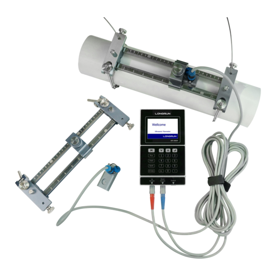
LRF-6000H Ultrasonic flowmeter Transmitter Installation Take out the transmitter. Shown from left to right on the top of model 6000H are the upstream transducer connector, downstream transducer connector, and 4~20mA output connector. On the left side of the transmitter, are the power recharging and the power switch. One rechargeable 11.1V Lithium battery and matching battery charger are coming with. -
Page 7: Powering On
LRF-6000H Ultrasonic flowmeter Powering On When power on, the self-diagnosis program will start to run. If any error is detected, an error code will be displayed on the screen (see Error Codes and Solutions). After that, the system will run automatically using the programmed parameters. If it is the first time to use or install on a new site, new installation site parameters are needed to enter. -
Page 8: Main Screen
LRF-6000H Ultrasonic flowmeter Main screen When power on, the self-diagnosis program will automatically start to run. First comes the welcome screen: Signal Quality (SQ value), Net Totalizer (NET), Positive Totalizer (POS), Negative Totalizer (NEG), Flow Velocity (Vel.). Note: SQ value is short for Signal Quality. It indicates the level of the signal detected. SQ value is indicated by numbers from 0~99. - Page 9 LRF-6000H Ultrasonic flowmeter Display the velocity and flow curve. The data will be updated only stay in this screen. Display the signal strength, Date and time, Signal quality, Speed ratio (TOM/TOS), Sound Velocity, Total transit time (TOF), Delta time (DT). About TOM/TOS: Display the ratio of actual measured transmission time to calculated transmission time according to customer requirements.
-
Page 10: Setup Menu
LRF-6000H Ultrasonic flowmeter Setup Menu Press will display Setup menu. The following options are available (by pressing buttons), select the option Setup Menu – Measurement parameter For example, to measure a DN1000 PVC pipe with medium as water and n o l iner. Input settingss are as above. -
Page 11: Setup Menu - System Setting
LRF-6000H Ultrasonic flowmeter 3. Fluid type: 0. Water 3. Gasoline 6. Propane 1. Sea Water 4. Fuel Oil 7. Butane 2. Kerosene 5. Crude Oil 8. Other 4. Transducer Type: 0. Standard 1. Wetted45 2. Wetted23 5. Transducer installing: 0. V Method 2. - Page 12 LRF-6000H Ultrasonic flowmeter 2. The following units are available: 0. m3 3. IG 6. UB 1. L 4. mg 7. IB 2. GAL 5. cf 8. OB 3. Total RESET: ENT TO RESET: reset all totalizer System RESET: factory reset Note: Except during the initial installation, it is generally not necessary to activate this feature.
-
Page 13: Setup Menu - Calibration
LRF-6000H Ultrasonic flowmeter Setup Menu – Calibration 0. Scale factor: Scale factor refers to the ratio between “actual value” and “reading value”. For example, when the measurement is 2.00, and it is indicated at 1.98 on the instrument, the scale factor reading is 2/1.98. - Page 14 LRF-6000H Ultrasonic flowmeter Generally, 0.03m/s is recommended to enter as the low flow cutoff point. The low flow cutoff value has no relation to the measurement results once the velocity increases over the low flow cutoff value. 4. Manual zero point: This method is not commonly used.
-
Page 15: Setup Menu - Output Setting
LRF-6000H Ultrasonic flowmeter Setup Menu – Output setting 0. RS485 Setup: The window used to set serial ports. It’s for communications with other equipment. It connects with the equipment through serial ports. The parameters must be set to match with each other. Select the baud rata 9600, 19200, 38400, 56000, 57600, 115200. The second option is that in check, None. - Page 16 LRF-6000H Ultrasonic flowmeter frequency output, other functions are unavailable. The following signal options are available: 0. No Signal 4. POS Int Pulse 8. FO 1. Alarm #1 5. NEG Int Pulse 9. Not Using 2. Alarm #2 6. NET Int Pulse 3.
-
Page 17: Setup Menu - Energy Setting
LRF-6000H Ultrasonic flowmeter Setup Menu – Energy setting 0. Energy unit: 0. GJ 1. MBtu 2. KWh 3. MWh 4. RT 1. Temperature unit: 0. ℃ 1. ℉ 2. Flow site: 0. Inlet 1. Outlet Setup Menu – Historical data Review the historical flow data totalizer for any day in the last 64 days, any month in last 64 months and any year in the last 10 years. -
Page 18: Setup Menu - System Information
LRF-6000H Ultrasonic flowmeter Setup Menu – System information Display electronic serial number (ESN) of the flow meter, power on/off time, run time and flow rate. This ESN is the only one assigned to each flow meter when ready to leave factory. Setup Menu –... -
Page 19: Setup Menu - Flow Batch Controller (For Wall Mount Model)
LRF-6000H Ultrasonic flowmeter Setup Menu – Flow Batch controller (For wall mount model) Batch control can be carried out, and the total amount can be controlled and operated by button setting. Setup Menu – Language setting Language setting: 0. English; 1. Chinese Simplified; 2. Chinese Traditional Page 19 of 29... -
Page 20: Measurement Site Selection
LRF-6000H Ultrasonic flowmeter Measurement Site Selection When selecting a measurement site, it is important to select an area where the fluid flow profile is fully developed to guarantee a highly accurate measurement. Please follow these guidelines for selecting a proper measurement installation site: Choose a section of pipe, which is always full of liquid, such as a vertical pipe with flow in the upward direction or a full horizontal pipe. -
Page 21: Transducer Installation
LRF-6000H Ultrasonic flowmeter Transducer Installation Before installing the transducers, clean the pipe surface where the transducers are to be mounted. Remove any rust, scale or loose paint and make a smooth surface. Choose a section of sound conducting pipe for installing the transducers. Apply a wide band of sonic coupling compound down the center of the face of each transducer as well as on the pipe surface, and then attach the transducers to the pipe with the provided racks and tighten them firmly. -
Page 22: Method
LRF-6000H Ultrasonic flowmeter V Method The V method is considered as the standard method. It usually gives a more accurate reading and is used on pipe diameters from 25mm to 400mm (1” ~16”). It is convenient to install, but still requires proper installation of the transducers. It is in contact with the pipeline at the centerline of the pipeline, and the spacing on both sides of the centerline is equal. -
Page 23: N Method (Not Commonly Used)
LRF-6000H Ultrasonic flowmeter N Method (not commonly used) With the N method, the sound waves traverse the fluid twice and bounce three times off the pipe walls. It is suitable for small pipe diameter measurement. The measurement accuracy can be improved by extending the transit distance with the N method (commonly used). -
Page 24: Transducer Mounting Inspection
LRF-6000H Ultrasonic flowmeter Transducer Mounting Inspection Check if the transducers are installed properly and accurate and strong enough ultrasonic signal to make sure proper operation and high reliability of the transducers. Confirm them by checking the detected signal strength, total transit time, delta time and transit time ratio. The installation condition directly influences the flow value accuracy and system long-time running reliability. -
Page 25: Transit Time Ratio
LRF-6000H Ultrasonic flowmeter Transit Time Ratio Transit Time Ratio indicates if the transducer mounting spacing is accurate. The normal transit ± time ratio should be 100 3 if the installation is proper. Check it in “Main Menu”. ± If the transit time ratio is over 100 3, it is necessary to check: (1) If the parameters (pipe outside diameter, wall thickness, pipe material, liner, etc.) have been set correctly,... -
Page 26: Operating Instructions
LRF-6000H Ultrasonic flowmeter Operating Instructions Zero Cut When static flow with zero flow rate, set a zero point in the flow meter. It is indicated as zero when the measurement flow rate reach to zero. When necessary to establish the true zero flow condition, set it in the flow meter. -
Page 27: 20Ma Current Loop Calibration
LRF-6000H Ultrasonic flowmeter 4~20mA Current Loop Calibration With a current loop output exceeding 0.5% accuracy, the flow meter is programmable and configurable with multiple output modules such as 4~20mA. Select “Setup Menu – Input and Output setting” In this window, to calibrate 4mA flow value and 20mA flow value. For example: If the flow range is between 0~1000m3/h, input 0 and 1000. -
Page 28: Appendix Error Codes And Solutions
LRF-6000H Ultrasonic flowmeter Appendix Error Codes and Solutions Code Display Cause Solution System Normal System normal No errors Signal not detected Attach transducer to the pipe and tighten it securely. Spacing is not correct Apply a plenty of coupling between the compound on transducer transducers or not... - Page 29 LRF-6000H Ultrasonic flowmeter Longrun Industrial Instrument Co.,Ltd 24hours service:+86-186-5435-6933 Tel:+86-543-3382666 Fax:+86-543-3615999 E-mail:info@ultrasonicscn.com Website:www.longrun-flowmeter.com This instruction is recyclable Page 29 of 29...
Need help?
Do you have a question about the LRF-6000H Series and is the answer not in the manual?
Questions and answers