
Related Manuals for Longrun LRF-3000S


Summary of Contents for Longrun LRF-3000S
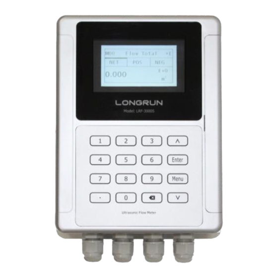
- Page 1 LRF-3000S Ultrasonic Transit-time Flow meter Revision:1.0.0 UpdateRecord:October,2018...
- Page 2 LRF-3000S Ultrasonic Transit-time Flow meter Notice Thank you for choosing the LRF-3000S Ultrasonic Flow meter. Place read the instruction manual carefully before you use the flow meter to avoiding the damage to the flow meter or improper use. Warning May cause injury.
-
Page 3: Table Of Contents
LRF-3000S Ultrasonic Transit-time Flow meter Content Product Overview ............................-4- 1.1. Introduction............................-4- 1.2. Features of LRF-3000S ........................-4- 1.3. Theory of Operation......................... -4- 1.4. Specifications ..........................- 5 - Connection ..............................- 6 - 2.1. Wire Connecting ..........................- 6 - 2.1.1. - Page 4 LRF-3000S Ultrasonic Transit-time Flow meter 5.7. Frequency Output ........................- 18 - 5.8. Totalizer Pulse Output ......................... - 19 - 5.9. Alarm Programming ........................- 19 - 5.10. 4-20mA Analog Output Calibration ..................... - 19 - 5.11. SD Card Operation ........................- 20 - 5.1.1.
-
Page 5: Product Overview
At the same time LRF-3000S has our unique calculate software to ensure the high accuracy and low velocity response. -
Page 6: Specifications
LRF-3000S Ultrasonic Transit-time Flow meter 1.4. Specifications Performance specifications Flow Rage 0 ft/s ~ ± 40 ft/s ( 0 m/s ~ ± 12 m/s ). Accuracy ± 1.0% of measured value. Repeatability 0.2%. 1″ ~ 48″ ( 25 mm ~ 1200 mm ). -
Page 7: Connection
LRF-3000S Ultrasonic Transit-time Flow meter 2. Connection 2.1. Wire Connecting 2.1.1. Power supply option Customers should pay special attention to specify the desired power supply when wiring. Factory standard power supply is 10~36VDC/1A max. To ensure the transmitter can work normally, please pay attention to the followings when wiring: Ensure that power connections are made in accordance with the specifications shown on the transmitter. -
Page 8: Powering On
LRF-3000S Ultrasonic Transit-time Flow meter Downstream sensor - Blue OCT OUT+ OCT Output OCT OUT- I OUT+ 40~20mA Output I OUT- Analog Signal Input ( Only Energy Meter ) RS232 Output RS485 Output IN1+ Temperature sensor water inline + IN1-... -
Page 9: Keypad Functions
LRF-3000S Ultrasonic Transit-time Flow meter will be carried out as usual, no matter in which display window. 2.3. Keypad Functions Numbers “0~9” and “.” Input Numbers or Menu Code “ ”Backspace or delete characters to the left or back to the previous menu. -
Page 10: Quick Start
LRF-3000S Ultrasonic Transit-time Flow meter 3. Quick start 3.1. Basic settings For example, let us you have a pipe of 200mm outer diameter、4mm pipe thickness, measuring medium is water, Pipe Material is PVC with no Liner, These parameters should be operated as follows: Step1. -
Page 11: Measurement Site Selection
LRF-3000S Ultrasonic Transit-time Flow meter Step4. Transducer Type Ttransducer Find M13, select the transducer type, here we select the 1. Clamp-On-D, our standard clamp on type Type Method Mode transducer. Press the “ Enter” to confirm. Option 0.Clamp-On Ttransducer Step 5. Transducer Mounting Methods Use “... - Page 12 LRF-3000S Ultrasonic Transit-time Flow meter ⚫ Ensure enough straight pipe length at least equal to the figure shown below for the upstream and downstream transducers installation. Try to avoid Ensure enough straight pipe length at least equal to the figure shown below for the upstream and downstream transducers installation.
- Page 13 LRF-3000S Ultrasonic Transit-time Flow meter - 12 -...
-
Page 14: Transducer Installation
LRF-3000S Ultrasonic Transit-time Flow meter 4. Transducer Installation 4.1. Transducer Installation Please make sure the pipe surfaces where the transducers are to be mounted are all clean. Including the rust, scale or loose paint to have a smooth surface. Choose the section and don’t forget apply the coupling compound. Apply... -
Page 15: Z Method
LRF-3000S Ultrasonic Transit-time Flow meter 4.1.4. Z Method The signal transmitted in a Z method installation has less attenuation than a signal transmitted with the V method When the pipes are too large, there are some suspended solid in the fluid, or the scaling and liner are too thick. -
Page 16: Signal Strength
LRF-3000S Ultrasonic Transit-time Flow meter to ensure proper operation and high reliability of the transducer. It can be confirmed by checking the detected signal strength, total transit time, delta time as well as transit time ratio. The "mounting" condition directly influences the flow value accuracy and system long-time running reliability. In most instances, only apply a wide band of sonic coupling compound lengthwise on the face of the transducer and stick it to the outside pipe wall to get good measurement results. -
Page 17: Warnings
LRF-3000S Ultrasonic Transit-time Flow meter 4.2.5. Warnings Pipe parameters entered must be accurate; otherwise the Flow meter will not work properly. During the installation, apply enough coupling compounds in order to stick the transducers onto the pipe wall. While checking the signal strength and Q value, move the transducers slowly around the mounting site until the strongest signal and maximum Q value can be obtained. -
Page 18: Operating Instructions
LRF-3000S Ultrasonic Transit-time Flow meter 5. Operating Instructions 5.1. System Normal Identification If the letter "*R" displays on the screen, it indicates system normal. If the letter "D" is displayed, it indicates that system is adjusting the signal gain prior to the measurement. Also, it means system normal. -
Page 19: System Lock
LRF-3000S Ultrasonic Transit-time Flow meter 5.5. System Lock System lock is intended to prevent operation error due to tampering by unauthorized personnel. M54 is for system lock, unlock it by using the selected password only. If "lock” is displayed on the screen, then enter the correct password. -
Page 20: Totalizer Pulse Output
LRF-3000S Ultrasonic Transit-time Flow meter 5.8. Totalizer Pulse Output Each time the flow meter reaches a unit flow, it may generate a totalizer pulse output to a remote counter. The totalizer pulse output can be transmitted through OCT or a relay. Therefore, it is necessary to configure OCT and the relay accordingly. -
Page 21: Sd Card Operation
LRF-3000S Ultrasonic Transit-time Flow meter current of current loop and adjust the displayed numbers at the same time. Watch the ammeter until it reads 4.00. Stop at this point, the 4mA has been calibrated. Use “ ” and “ ” to switch. Calibrate the current loop 20mA output. The method is the same as 4mA calibration. -
Page 22: Esn
LRF-3000S Ultrasonic Transit-time Flow meter Attention: Do not remove the SD card from the reader while actively working with the data. Data should be saved and stored in a separate location on the PC, and then processed form that file location. -
Page 23: Windows Display Explanations
LRF-3000S Ultrasonic Transit-time Flow meter 6. Windows Display Explanations 6.1. Windows Display Codes Easy Introduction A class of the menu Display M00 Flow Totalizer Value and Condition M01 Flow Rate *R- System Normal *E - Signal Not Detected M02 Hot... - Page 24 LRF-3000S Ultrasonic Transit-time Flow meter M34 Relay Settings Input and Output Settings M35 Alarm Value Settings M36 Ration M37 Micro SD Settings (option ) Flow Unit Opinions M40 Toggle Units M41 Flow Units M42 Energy Units M43 Temperature Units System Settings...
-
Page 25: Display Explanations
LRF-3000S Ultrasonic Transit-time Flow meter 6.2. Display Explanations Flow Total Flow Total Display Net Totalizer. Display Positive totalizer. Display Negative totalizer. 123.4 to switch. Flow Total 123.4 Flow Rate Display the Flow Rate and Flow Total Display the Velocity. Flow Rate... - Page 26 LRF-3000S Ultrasonic Transit-time Flow meter Heat Rate Heat Display the Heat Total. 100.2 Display the Heat Rate and the Inlet Water Temp and Outlet Water Temp. NOTE: 234.5 Instrument needs energy capacity. x 0.001 (E-3) x 0.01(E-2) x 0.1(E-1) x 1(E+0)
- Page 27 LRF-3000S Ultrasonic Transit-time Flow meter Status Signal Sound Time Status Display the Signal strength, the Upstream signal strength and Downstream signal strength. 80.0 80.1 Signal quality Q is indicated by 00 ~ 99. Therefore, 00 indicates the poorest signal while 99 indicates the best signal. Normally,...
- Page 28 LRF-3000S Ultrasonic Transit-time Flow meter Pipe settings Enter the pipe outer diameter; the pipe outer Pipe settings diameter must range from 10mm to 1200mm. Size Note: Enter Either pipe outer diameter or pipe outer perimeter 0.PVC Enter the pipe wall thickness. Pipe wall thickness is necessary.
- Page 29 LRF-3000S Ultrasonic Transit-time Flow meter Lining Enter liner thickness. Select the Liner Material. The following options are available: No liner Tar Epoxy Rubber Mortar PP Polypropylene Polystryol PS Polystyrene Polyester PE Polyethylene Ebonite Teflon Other Item 11 "Other" is available to enter other materials that are not included in previous ten items.
- Page 30 LRF-3000S Ultrasonic Transit-time Flow meter Transducer Ttransducer Select transducer type The following options are available: Type Method Mode 0. Clamp-On C Option 0.Clamp-On C 1. Clamp-On D 2. Clamp-On X 3. Plus-In 4. Plus-In X Select transducer Mounting Methods Three mounting methods are available: 0.
- Page 31 LRF-3000S Ultrasonic Transit-time Flow meter The damping factor ranges from 1 ~ 999 seconds.1 Damping indicates no damping; 999 indicates the maximum damping. The damping function will stabilize the flow display. Value Usually a damping factor of 3 to 10 is recommended in applications.
- Page 32 LRF-3000S Ultrasonic Transit-time Flow meter conditions when it is not preferable to use other Zero Settings methods. Enter the value manually to add to the measured value to obtain the actual value. For example: Cutoff Reset Offset Actual measured value =240 m Value Value Deviation =10 m...
- Page 33 LRF-3000S Ultrasonic Transit-time Flow meter Temperature Temperature Select Heat Input Options: 0. RTD Source SSTV 1. AI Option 0.RTD Use “ ” and “ ” to switch Temperature Sensitivity Setting When the delta temperature is less than the sensitivity set, energy will not be accumulated. Set the adjustable temperature range of 0℃...
- Page 34 LRF-3000S Ultrasonic Transit-time Flow meter The K factor is used to modify the measurement K Factor results. The user can enter a numerical value (other than "1") according to the actual calibration results. Value 1.000 Correction K-Array Correction Sectional Correction ON: Open the Sectional Correction Function;...
- Page 35 LRF-3000S Ultrasonic Transit-time Flow meter Statistic Analysis Reset Option 0.ON/1.OFF Value 4.500 Reset Option 0.Auto Value 4.500 RS232/RS485 Serial Port Setting 0. 2400 None RS232/RS485 1. 4800 None 2. 9600 None 3. 19200 None Option 0.2400 None 4. 38400 None 5.
- Page 36 LRF-3000S Ultrasonic Transit-time Flow meter AI Settings LowerL UpperL 1000.0 CL Setting Current Loop Mode Options CL Settings Select the CL Range value Set the CL output value according to the flow value Mode Range Check at 4mA or 0MA.
- Page 37 LRF-3000S Ultrasonic Transit-time Flow meter The following signal options are available: OCT Settings a. Flow Rate b. POS Total Mode Range Check c. NEG Total Option a.Flow Rate d. NET Total e. Energy Rate Frange 0-5000 Hz Heat Total g. Cool Total h.
- Page 38 LRF-3000S Ultrasonic Transit-time Flow meter a. No Signal b. *E Relay Settings c. Reverse d. Alarm1 e. Alarm2 Option a.No Signal Ration g. POS Total h. NEG Total NET Total Not Using Alarm Setting Enter the Lower \ alarm value, any of the measured...
- Page 39 LRF-3000S Ultrasonic Transit-time Flow meter Following is the Ration opinions: Ration a. Key CTRL b. AI1 CTRL c. AI2 CTRL Option a.Key CTRL d. Uart CTRL Value 1000.0 Micro SD Following is the opinions for the record. Micro SD a. No Energy b.
- Page 40 LRF-3000S Ultrasonic Transit-time Flow meter Factory default is Cubic Meters/hour. Flow Unit x 0.001 (E-3) x 0.01(E-2) Unit MULT. x 0.1(E-1) x 1(E+0) Option d. *1 x 10(E+1) x 100(E+2) x 1000(E+3) 10000(E+4) Energy Unit The following Energy units are available:...
- Page 41 LRF-3000S Ultrasonic Transit-time Flow meter TEMP Unit Serial Number Display electronic serial number (S/N) of the instrument. This S/N is the only one assigned to each flow meter ready to leave the factory. The 。 Option factory uses it for files setup and for management by the user.
- Page 42 LRF-3000S Ultrasonic Transit-time Flow meter Language System Lock Lock the instrument. Once the system is locked, any Option 0.English modification to the system is prohibited, but the parameter is readable. Entering your designated password correctly can be the only way to "Unlock".
- Page 43 LRF-3000S Ultrasonic Transit-time Flow meter Running Time CL Adjust This menu is for the 4-20mA calibration; enter the Value pass word to adjust. CL Adjust RTD Adjust This menu is for the RTD calibration; enter the pass word to adjust.
- Page 44 LRF-3000S Ultrasonic Transit-time Flow meter AI adjust Enter to go 20mA Enter to go AI adjust Enter to go 20mA Enter to go - 43 -...
-
Page 45: Error Diagnoses
LRF-3000S Ultrasonic Transit-time Flow meter 7. Error Diagnoses The ultrasonic flow meter has advanced self-diagnostics functions and displays any errors in the upper right corner of the LCD via definite codes in a date/time order. Some errors can be detected during normal operation. -
Page 46: Frequently Asked Questions And Answers
LRF-3000S Ultrasonic Transit-time Flow meter 7.2. Frequently Asked Questions and Answers Question: New pipe, high quality material, and all installation requirements met: why still no signal detected? Answer: Check pipe parameter settings, installation method and wiring connections. Confirm if the coupling compound is applied adequately, the pipe is full of liquid, transducer spacing agrees with the screen readings and the transducers are installed in the right direction. -
Page 47: Appendix3 - Serial Interface Network Use And Communications Protocol
LRF-3000S Ultrasonic Transit-time Flow meter 8. Appendix3 – Serial Interface Network Use and Communications Protocol 8.1. Overview The flow meter has perfect communication protocol. It can also be connected to a RS-485 Modbus . Two basic schemes can be chosen for networking, i.e. the analog current output method only using the flow meter or the RS232 communication method via serial port directly from the flow meter. -
Page 48: Direct Connection Via Rs232 To The Host Device
LRF-3000S Ultrasonic Transit-time Flow meter 8.3. Direct connection via RS232 to the host device See the below list of flowmeter serial port definitions. 8.4. Communications protocol and the use The flow meter supports these three communication protocols: FUJI Protocol, MODBUS-C Protocol, MODBUS-I Protocol. - Page 49 LRF-3000S Ultrasonic Transit-time Flow meter RT-(cr)(lf) ± ddddddd.d± d(cr) Return negative accumulative flow RTN(cr)(lf) Return net accumulative flow ± ddddddd.d± d(cr) RTH(cr)(lf) ± ddddddd.d± d(cr) Return net accumulative energy(hot) RT-(cr)(lf) Return net accumulative energy(cold) ± ddddddd.d± d(cr) RER(cr)(lf) Return instantaneous energy value ±...
-
Page 50: Modbus-I Communication Protocol
LRF-3000S Ultrasonic Transit-time Flow meter verification. The method of verification is to add all of the data back to the data, which is cumulative and binary, and its low 8-bit binary data is taken. E.g. The return information of the RT(cr)(lf) is :+1234567E+0m3(cr)(lf), (the relative binary system data is 2BH,31H,32H,33H,34H,35H,36H,37H,45H,2BH,30H,6DH,33H,20H,0DH,... - Page 51 LRF-3000S Ultrasonic Transit-time Flow meter 1 byte 1 byte 1 byte N*x2 byte 2 bytes 0x01 ~ 0xF7 0x03 2xN* N*x2 ( Data ) CRC ( Verify ) N* = Data register number 3. MODBUS Protocol function code 0x06 usage...
- Page 52 LRF-3000S Ultrasonic Transit-time Flow meter 0x01 0x06 0x10 0x03 0x00 0x02 0xFC 0xCB Flow meter Address Function Code Register Address Register Number CRC Verify Code 4. Error Check The flow meter only returns one error code 0x02 which means data first address in error.
- Page 53 LRF-3000S Ultrasonic Transit-time Flow meter Negative total – high word $000C 40013 Negative total – exponent $000D 40014 16 bits int. Net total – low word $000E 40015 32 bits int. Net total – high word $000F 40016 Net total – exponent...
- Page 54 LRF-3000S Ultrasonic Transit-time Flow meter Flow rate unit –char 3,4 $003E 40063 Flow total unit – char 1,2 String $003F 40064 Energy rate unit – char1,2 String Note 2 $0040 40065 Energy rate unit – char 3,4 $0041 40066 Energy total unit – char 1,2...
- Page 55 LRF-3000S Ultrasonic Transit-time Flow meter 0. "m3" -Cubic Meter -Liters 1. "l" -Gallons 2. "ga" -Imperial Gallons 3. "ig" 4. "mg" -Million Gallons -Cubic Feet 5. "cf" -US Barrels 6. "ba" -Imperial Barrels 7. "ib" -Oil Barrels 8. "ob" The following energy units are available:...
-
Page 56: Appendix6 - Flow Application Data
LRF-3000S Ultrasonic Transit-time Flow meter 9. Appendix6 - Flow Application Data 9.1. Sound Velocity for Various Materials Commonly Used Pipe Material Sound Velocity (m/s) Liner Material Sound Velocity Steel 3206 Teflon 1225 2286 Titanium 3150 Aluminum 3048 Cement 4190 Bitumen... -
Page 57: Sound Velocity In Water (1 Atm) At Different Temperatures
LRF-3000S Ultrasonic Transit-time Flow meter 9.2. Sound Velocity in Water (1 atm) at different temperatures t(℃) v(m/s) t(℃) v(m/s) t(℃) v(m/s) 1402.3 1517.7 1554.3 1407.3 1519.7 1554.5 1412.2 1521.7 1554.7 1416.9 1523.5 1554.9 1421.6 1525.3 1555.0 1426.1 1527.1 1555.0 1430.5 1528.8... - Page 58 LRF-3000S Ultrasonic Transit-time Flow meter Longrun Industrial Instrument Co.,Ltd 24hours service:+86-186-5435-6933 Tel:+86-543-3382666 Fax:+86-543-3615999 E-mail:info@ultrasonicscn.com Website:www.longrun-flowmeter.com This instruction is recyclable - 57 -...
Need help?
Do you have a question about the LRF-3000S and is the answer not in the manual?
Questions and answers