
Related Manuals for Davis Instruments Vantage Vue 6242


Summary of Contents for Davis Instruments Vantage Vue 6242
- Page 1 Sensor Suite Installation Manual 3465 Diablo Ave., Hayward, CA USA 510.732.9229 • www.davisinstuments.com...
-
Page 2: Table Of Contents
Connect the equipment into an outlet on a circuit different from that to which the receiver is connected. • Consult the dealer or an experienced radio/TV technician for help. Changes or modification not expressly approved in writing by Davis Instruments may void the warranty and void the user's authority to operate this equipment. FCC ID: IR2DWW6357... -
Page 3: Introduction
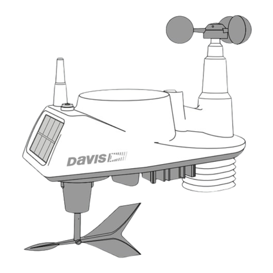
Introduction The Vantage Vue® wireless sensor suite collects outside weather data and sends the data wirelessly to a Vantage Vue console via a low-power radio. The sensor suite is solar- powered and includes a battery back-up. The Vantage Vue sensor suite contains a rain collector, temperature/humidity sensor, anemometer, and wind vane. -
Page 4: Hardware
Hardware Hardware included with the Vantage Vue sensor suite: Tools Needed U-Bolt • Adjustable wrench or 7/16” (11 mm) Debris screen wrench Backing plate • Compass or local area map 1/4” lock washers 0.05” Allen wren 1/4” hex nuts Note: If any of the hardware components are missing or not included, contact Customer Service toll free at 1-800-678-3669 about receiving replacement hardware or other components. -
Page 5: Attach The Wind Cups To The Anemometer
Attach the Wind Cups to the Anemometer The Vantage Vue anemometer measures wind speed. The wind cups are mounted on the anemometer shaft on the top of the sensor suite assembly. 1. Gently slide the wind cup assembly down onto the anemometer’s Install cups onto Tighten set screw stainless steel shaft. -
Page 6: Install The Rain Collector Tipping Spoon Assembly
Install the Rain Collector Tipping Spoon Tipping spoon Assembly assembly slot 1. Locate the tipping spoon assembly slot on the underside of the sensor suite base. 2. Insert the wider end of the tipping spoon assembly into the slot first, sliding it under the raised lip of the slot. -
Page 7: Advanced Installations: Confirm The Transmitter Id
IDs. The default transmitter ID for both the sensor suite and the Vantage Vue console is 1. Change the transmitter ID if another Davis Instruments wireless weather station is operating nearby and already uses transmitter ID 1, or if you have an optional Anemometer Transmitter Kit with ID 1. -
Page 8: Verify Data From The Sensor Suite
1. Push and hold the transmitter ID button until the LED begins flashing quickly. This indicates it is in the setup mode. 2. Release the button, and the LED will go dark. 3. Push the button the number of times equal to your desired new transmitter ID. That is, if you want to change the ID to 3, push the button three times;... -
Page 9: Installing The Sensor Suite
Installing the Sensor Suite Choosing a Location for the Sensor Suite The sensor suite assembly includes the rain collector, wind vane, anemometer, temperature and humidity sensors, radiation shield, and SIM housing. You will use the U-bolt and associated nuts and washers that are included with your sensor suite mounting hardware package to install the sensor suite on a pole. -
Page 10: Mounting The Sensor Suite
The Vantage Vue sensor suite can only be mounted on the top of a pole or rod. Note: A mounting pole is not included with your Vantage Vue sensor suite and must be purchased separately, either from Davis Instruments or from your local hardware retailer. - Page 11 Sensor Suite Installation Guidelines Recommended Accessories for Pole Mounting • Use the Mounting Tripod (#7716) for easiest mounting. • Use the Mounting Pole Kit (#7717) to raise the installation height of the sensor suite by up to 37.5" (0.95 m). General Guidelines for Installing on a Pole •...
-
Page 12: Finishing The Installation
Sensor Suite Installation Guidelines 7. If you are in the Northern Hemisphere, rotate the sensor suite on the pole so that the solar panel is facing south; if you are in the Southern Hemisphere, rotate the sensor suite so that the solar panel is facing north. -
Page 13: Maintenance And Troubleshooting
Maintenance and Troubleshooting Maintenance Note: If you are using WeatherLink Live, it is a good idea to power it down before maintaining your sensor suite so that it does not collect erroneous data during the maintenance steps. Cleaning the Radiation Shield The outer surface of the radiation shield should be cleaned when there is excessive dirt and build-up on the plates. - Page 14 Interference has to be strong to prevent the console from receiving a signal while in the same room as the sensor suite. • There is a problem with the Vantage Vue console. 7. If a problem with receiving the wireless transmission still exists, please contact Technical Support. Note: See “Contacting Davis Instruments” on page 13.
- Page 15 How you site the sensor suite and anemometer can also make a big difference. If you have questions, contact Davis Technical Support. Contacting Davis Instruments If you have questions about the sensor suite or Vantage Vue system, or encounter problems installing or operating the weather station, please contact Davis Technical Support.
-
Page 16: Appendix A: Specifications
Appendix A: Specifications See complete specifications for your Vantage Vue station on our website: www.davisinstruments.com Integrated Sensor Suite (ISS) Specifications Operating Temperature........-40° to +150°F (-40° to +65°C) Non-operating (Storage) Temperature ....-40° to +158°F (-40° to +70°C) Current Draw (ISS SIM only)......0.20 mA (average), 30 mA (peak) at 3.3 Solar Power Panel (ISS SIM) ......
Need help?
Do you have a question about the Vantage Vue 6242 and is the answer not in the manual?
Questions and answers