Advertisement
Quick Links
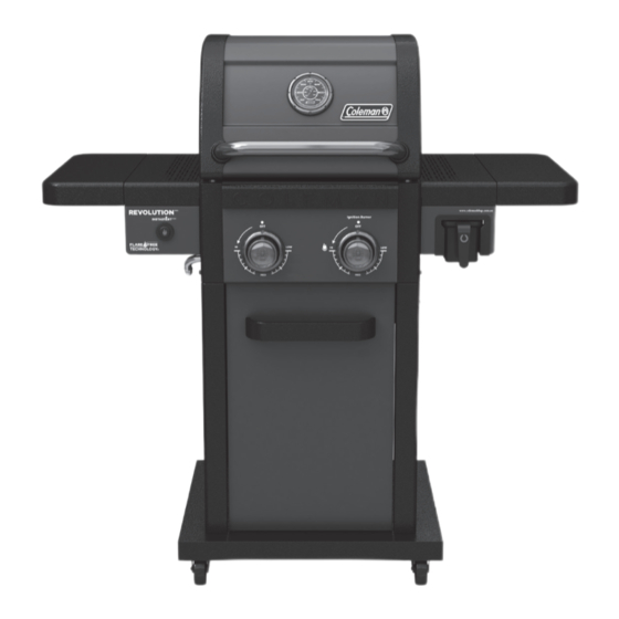
REVOLUTION
TM
2 BURNER
ASSEMBLY MANUAL
G36324
LIMITED 5-YEAR WARRANTY
AGA 9138G
Read and save manual for future reference.
Assemble your grill immediately. Missing or damaged parts
should be claimed within 30 days of purchase.
For product inquiries, parts, warranty and troubleshooting support,
please call 1300 659 489.
www.colemanbbqs.com.au
Manual Revision #: 2023.07.18 MK
Advertisement

Related Manuals for Coleman REVOLUTION G36324


Summary of Contents for Coleman REVOLUTION G36324
- Page 1 REVOLUTION 2 BURNER ASSEMBLY MANUAL G36324 LIMITED 5-YEAR WARRANTY AGA 9138G Read and save manual for future reference. Assemble your grill immediately. Missing or damaged parts should be claimed within 30 days of purchase. For product inquiries, parts, warranty and troubleshooting support, please call 1300 659 489.
- Page 2 H E A V Y A R T I C L E N E E D S 2 T O L I F T THIS MANUAL MUST REMAIN WITH THE PRODUCT AT ALL TIMES To ORDER non-warranty replacement parts or accessories, or to register your warranty, please visit us on the web at www.colemanbbqs.com.au CAUTION...
-
Page 3: Hardware Pack
HARDWARE PACK No. Description Part Number Qty. TOOLS NEEDED FOR ASSEMBLY 1/4"-20UNCx50 Screw 20120-13050-250 • #2 Phillips screwdriver (long and short) 1/4"-20UNCx38 Screw 20120-13038-250 1/4''-20UNCx16 Screw 20120-13016-250 • 1/4” Slotted screwdriver (long and short) 1/4’’-20UNC Screw G353-0014-9000 • Adjustable wrench NO.10-24UNC x13 Screw 20124-10013-250 •... - Page 4 PARTS LIST G36324 Item No. Qty. Description Part No. Item No. Qty. Description Part No. Top Lid Assembly G363-8200-01 Side Shelf Table G363-7200-02 Top lid Left side panel G363-0001-01 Side Shelf Fascia, Left G363-7300-02 Top lid Right side panel G363-0002-01 Side Shelf Table Rear Brace, G363-1000-01 Left...
- Page 5 EXPLODED DIAGRAM FOR G36324 Extras Assembly Safe Use Manual & Care Hardware Manual Pack...
- Page 6 ASSEMBL Y INSTRUCTIONS TIP: 6 1 2 One time assembly tool.
- Page 7 ASSEMBL Y INSTRUCTIONS...
- Page 8 ASSEMBL Y INSTRUCTIONS...
- Page 9 ASSEMBL Y INSTRUCTIONS TIP: Count all 4 screws as shown. TIP: Count all 4 screws as shown.
- Page 10 ASSEMBL Y INSTRUCTIONS TIP: Ensure correct assembly position as shown below. TIP: Attach Ground Wire CE4 to EA wall behind the Electronic Ignition Assembly CE1. View from the back.
- Page 11 ASSEMBL Y INSTRUCTIONS...
- Page 12 ASSEMBL Y INSTRUCTIONS...
- Page 13 ASSEMBL Y INSTRUCTIONS...
- Page 14 ASSEMBL Y INSTRUCTIONS WARNING: WATCH YOUR HANDS!
- Page 15 ASSEMBL Y INSTRUCTIONS TIP: Ensure that the rubber side of the rubberized washer makes contact with the burner box. TIP: Ensure holes on the bottom.
- Page 16 ASSEMBL Y INSTRUCTIONS...
- Page 17 ASSEMBL Y INSTRUCTIONS TIP: 1.Ensure that the rubber side of the rubberized washer makes contact with the burner box. 2.Only tighten screw halfway.
- Page 18 ASSEMBL Y INSTRUCTIONS TIP: Only tighten screw halfway. 6 10 TIP: Tighten screws.
- Page 19 ASSEMBL Y INSTRUCTIONS TIP: Tighten screws. TIP: Tighten screws.
- Page 20 ASSEMBL Y INSTRUCTIONS Front view TIP: Ensure wire are fully connected.
- Page 21 ASSEMBL Y INSTRUCTIONS Electronic Ignition Wire Assembly Locate the two instastart ignition wires(CE3) under the control panel (CG), attached to the manifold (CA). Connect wires to the Electronic ignition box, labelled CE3 in the diagram below. After, connect the main burner electrode wire to the Electronic ignition box, labelled CC in the diagram below.
- Page 22 ASSEMBL Y INSTRUCTIONS...
- Page 23 ASSEMBL Y INSTRUCTIONS TIP: 1.Ensure that the rubber side of the rubberized washer makes contact with the burner box. 2.Only tighten screw halfway. TIP: Only tighten screw halfway. TIP: Tighten screws.
- Page 24 ASSEMBL Y INSTRUCTIONS TIP: Tighten screws. TIP: Tighten screws.
- Page 25 ASSEMBL Y INSTRUCTIONS TIP: Start with the middle screw.
- Page 26 ASSEMBL Y INSTRUCTIONS Support Bracket A (DF) Support Bracket B (DG) Support Bracket A Support Bracket B (DF) (DG)
- Page 27 ASSEMBL Y INSTRUCTIONS...
- Page 28 ASSEMBL Y INSTRUCTIONS TIP: Ensure that all wires pass through the Left Heat Shield gap.
- Page 29 ASSEMBL Y INSTRUCTIONS...
- Page 30 ASSEMBL Y INSTRUCTIONS TIP: Remove the Ignition Battery Cover and then install the Ignition Box. TIP: All wires go through the gap.
- Page 31 ASSEMBL Y INSTRUCTIONS...
- Page 32 ASSEMBL Y INSTRUCTIONS...
- Page 33 ASSEMBL Y INSTRUCTIONS...
- Page 34 ASSEMBL Y INSTRUCTIONS...
- Page 35 ASSEMBL Y INSTRUCTIONS...
- Page 36 ASSEMBL Y INSTRUCTIONS...
- Page 37 ASSEMBL Y INSTRUCTIONS FOR PROPANE MODEL ONLY. www.colemanbbqs.com.au...
-
Page 38: Additional Warnings
ADDITIONAL WARNINGS You have now completed the Assembly of your COLEMAN® REVOLUTION™ BARBECUE. NEXT STEPS: 1. Position your BARBECUE 2. Read SAFE USE & CARE MANUAL 3. Perform Grill Safety Check-list WARNING: WARNING HOT SURFACES: FOR YOUR FAMILY’S SAFETY, DO NOT ATTEMPT TO LIGHT... - Page 39 ©2023 The Coleman Company, Inc. Coleman are registered trademarks of ® The Coleman Company, Inc. used under license. www.colemanbbqs.com.au...
Need help?
Do you have a question about the REVOLUTION G36324 and is the answer not in the manual?
Questions and answers