Table of Contents
Advertisement
Advertisement
Table of Contents

Related Manuals for Chroma 66201


Summary of Contents for Chroma 66201
- Page 1 Digital Power Meter 66201/66202 Quick Start Guide...
- Page 2 Digital Power Meter 66201/66202 Quick Start Guide Chroma DIGITAL POWER METER 66202 MODEL GO/NG Shunt PASS Limit Vpk+ THDv FAIL Meas Vpk- Is/Trig Hold CURRENT VOLTAGE SYSTEM SHUNT Ipk+ Ipk- Hold Cali 0.01 AUTO AUTO AUTO Trig / Setup Enter Version 1.0...
- Page 3 Legal Notices The information in this document is subject to change without notice. Chroma ATE INC. makes no warranty of any kind with regard to this manual, including, but not limited to, the implied warranties of merchantability and fitness for a particular purpose. Chroma ATE INC. shall not be held liable for errors contained herein or direct, indirect, special, incidental or consequential damages in connection with the furnishing, performance, or use of this material.
- Page 4 Any recommendations made by Chroma for use of its products are based upon tests believed to be reliable, but Chroma makes no warranty of the results to be obtained. This warranty is in lieu of all other warranties, expressed or implied, and no representative or person is authorized to represent or assume for Chroma any liability in connection with the sale of our products other than set forth herein.
- Page 5 “ ” indicates that the level of the specified chemical substance exceeds the threshold level specified in the standards of SJ/T-11363-2006 and EU 2005/618/EC. Chroma is not fully transitioned to lead-free solder assembly at this moment; however, most of the components used are RoHS compliant.
-
Page 8: Table Of Contents
Digital Power Meter 66201/66202 Quick Start Guide Table of Contents Overview..................1 Product Introduction ..............1 Inspection .................1 Ambient Environment ...............2 Power Line Connection ............2 Fuse..................3 Time for Warm-Up ..............4 Cleaning ...................4 Panel Description ..............5 Front Panel ................5 Rear Panel................8 Examining Firmware Version ...........9 Operation................10... -
Page 10: Overview
Product Introduction This 66201/66202 Digital Power Meter manual covers the product model of 66201 and 66202. 66201/66202 is a digital power meter with voltage and current auto ranging function that can identify PASS / FAIL of UUT based on the inputted specification. Its front panel has 4 sets of... -
Page 11: Ambient Environment
Digital Power Meter 66201/66202 Quick Start Guide Ambient Environment (1) Do not use the meter in a dusty or vibrating location. K ee p a wa y from the follow in gs: Do not expose it to sunlight or corrosive gas. Be sure... -
Page 12: Fuse
Digital Power Meter 66201/66202 Quick Start Guide MODEL NO . GPIB SERIAL NO . CAT II ALL INPUT 20Arms 500Vrms CONTROL AC LINE SIGNALS FUSE 0 Hz / 60 Hz 30 VA Max 500Vrms T500 m A/ 250V VOLTAGE RANGE... -
Page 13: Time For Warm-Up
Digital Power Meter 66201/66202 Quick Start Guide Time for Warm-Up All functions of this meter are active when it is powered on; however, to meet the accuracy listed in the specification it is suggested to warm-up for at least 60 minutes. -
Page 14: Panel Description
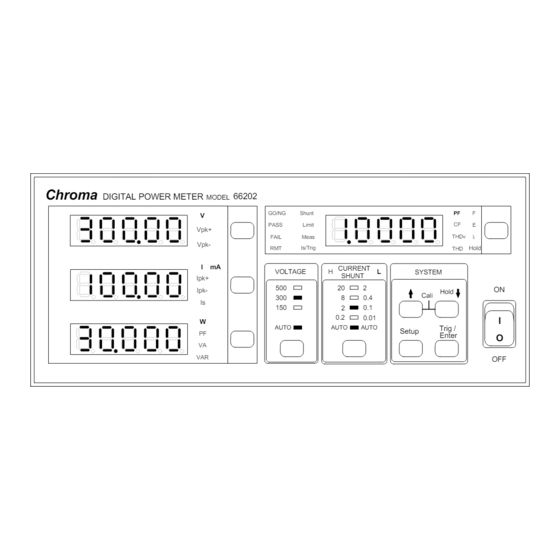
Panel Description Front Panel Figure 2-1 and Figure 2-2 show the front panel of 66201 and 66202 digital power meters with parts described from item (1) to (12) as listed below. For detail operation procedures, please see the User’s Manual in the CD attached to the shipment. - Page 15 Digital Power Meter 66201/66202 Quick Start Guide Chroma DIGITAL POWER METER 66202 MODEL GO/NG Shunt PASS Limit Vpk+ FAIL Meas THDv Vpk- Is/Trig Hold CURRENT VOLTAGE SYSTEM SHUNT Ipk+ Ipk- Hold Cali 0.01 AUTO AUTO AUTO Trig / Setup Enter...
- Page 16 (current RMS), Ipk+ (positive peak current) and Ipk- (negative peak current) only. 66201 Digital Power Meter provides the parameters of PF (Power Factor), CFi (Crest Factor of Current) and F (Frequency). 66201 Digital Power Meter has Limit and Meas function for setting.
-
Page 17: Rear Panel
Digital Power Meter 66201/66202 Quick Start Guide Rear Panel Figure 2-3 shows the rear panel of 66201/66202 digital power meter with parts described from item (1) to (9) as listed below. MODEL NO. GPIB SERIAL NO. CAT II ALL INPUT... -
Page 18: Examining Firmware Version
Digital Power Meter 66201/66202 Quick Start Guide Examining Firmware Version Power on the 66201/66202 Digital Power Meter. When the panel is in normal state, press Setup and Enter simultaneously. The screen shows: The Model No. is 66202, F/W version is 1.20 and FPGA program version is 1.00. -
Page 19: Operation
Connecting Test Device 3.2.1 Standard Connection 66201/66202 Power Meter has two types of connection. Its measurement theory is shown in Figure 3-1 (a) and (b). Unit Under Unit Under Test... - Page 20 The connection of Figure 3-1(b) is more accurate for voltage measurement, but the current measurement will add the leakage current from voltage meter. It is applicable for the UUT with medium or larger power. Its connection with 66201/66202 Power Meter is shown in Figure 3-3. MODEL NO.
-
Page 21: Connecting With A662003 Fixture
A C Source Figure 3-3 66201/66202 Power Meter Connecting Diagram (for Figure 3-1(b)) 3.2.2 Connecting with A662003 Fixture Figure 3-4 shows the connection of 66201/66202 Digital Power Meter and A662003 fixture. The connection of Figure 3-1(a) is applied by A662003 internally. -
Page 22: Test Function & Operation
250V / 15A SWITCH 250V / 15A To Power Meter Figure 3-4 Connection of 66201/66202 Digital Power Meter & A662003 Fixture WARNING Be sure the connecting cable of voltage and current are in correct position as it may cause the internal circuit to burnout if connected mistakenly. -
Page 23: Using Remote Control
Digital Power Meter 66201/66202 Quick Start Guide Using Remote Control Overview 66201/66202 provides GPIB and USB two kinds of remote control interfaces and all functions of panel keys can be controlled by these two interfaces. The USB interface supports 2.0/USB 1.1, while the GPIB interface is complied with IEEE-488 standard. -
Page 24: Definition Of Gpib Address
Digital Power Meter 66201/66202 Quick Start Guide Definition of GPIB Address The DIP switch on the rear panel of 66201/66202 defines the GPIB address. The definition is binary (Bit0~Bit4) with Address 1 ~ Address 30 for setting as shown below.
Need help?
Do you have a question about the 66201 and is the answer not in the manual?
Questions and answers