Table of Contents
Advertisement
Advertisement
Table of Contents

Related Manuals for Chroma 16502


Summary of Contents for Chroma 16502
- Page 3 Milliohm Meter 16502 User’s Manual Version 1.3 March 2017...
- Page 4 The information in this document is subject to change without notice. Chroma ATE INC. makes no warranty of any kind with regard to this manual, including, but not limited to, the implied warranties of merchantability and fitness for a particular purpose.
- Page 5 Any recommendations made by Chroma for use of its products are based upon tests believed to be reliable, but Chroma makes no warranty of the results to be obtained. This warranty is in lieu of all other warranties, expressed or implied, and no representative or person is authorized to represent or assume for Chroma any liability in connection with the sale of our products other than set forth herein.
- Page 6 Material Contents Declaration The recycling label shown on the product indicates the Hazardous Substances contained in the product as the table listed below. : See <Table 1>. : See <Table 2>. <Table 1> Hazardous Substances Lead Mercury Cadmium Hexavalent Polybrominated Selected Phthalates Chromium Biphenyls/...
- Page 7 “” indicates that the level of the specified chemical substance exceeds the threshold level specified in the standards of SJ/T-11363-2006 and EU Directive 2011/65/EU. Chroma is not fully transitioned to lead-free solder assembly at this moment; however, most of the components used are RoHS compliant.
-
Page 9: Safety Summary
Failure to comply with these precautions or specific WARNINGS given elsewhere in this manual will violate safety standards of design, manufacture, and intended use of the instrument. Chroma assumes no liability for the customer’s failure to comply with these requirements. -
Page 10: Safety Symbols
Safety Symbols DANGER – High voltage. Explanation: To avoid injury, death of personnel, or damage to the instrument, the operator must refer to the explanation in the instruction manual. High temperature: This symbol indicates the temperature is hazardous to human beings. Do not touch it to avoid any personal injury. -
Page 11: Revision History
Revision History The following lists the additions, deletions and modifications in this manual at each revision. Date Version Revised Sections Apr. 2010 Complete this manual. Jul. 2013 Add CE Declaration Modify the contents in the sections below: “Material Contents Declaration” Table 1-1 and 1-2 in the section of “Checking before Use”. -
Page 13: Table Of Contents
Milliohm Meter 16502 User’s Manual Table of Contents Preface........................1-1 An Overview of Product ................1-1 Summary of Specification ................1-1 Checking before Use ................... 1-1 Specification (15°C ~ 35°C RH ≤ 75%) ..............2-1 Measurement Function ................2-1 Accuracy ..................... 2-1 Zero ...................... - Page 14 Milliohm Meter 16502 User’s Manual Description of Handler Interface ................7-1 Description of Handler Interface Pins for BINNING........7-1 Description of Handler Interface Pins for COMPARE ........7-2 Descriptions of Temperature Measurement and Correction Function ....8-1 Description for Temperature Measurement Function ........8-1 8.1.1...
-
Page 15: Preface
The multi-functions testing device, ergonomics keyboard design, guided panel operation, extra-large LCD, and password protection makes the 16502 easy to operate and the test results are clearly showed on thr display. The basic accuracy is 0.05%. The measurement device (optional) can perform the calibration by keying-in the measuring parameter. - Page 16 Milliohm Meter 16502 User’s Manual Item 16502 Quick Start Power Cord Power Connector 16502 User’s Manual Name Guide Traditional 1.8M*1pc 3PIN to 2PIN* 1pcs CD*1 Chinese * 1pc Item AC 220V used Test Cable 16502 Quick Start AC 110V used Name 0.5A/250V Fuse...
-
Page 17: Specification (15°C ~ 35°C Rh ≤ 75%)
Specification Specification (15°C ~ 35°C RH ≤ 75%) Measurement Function Parameter: R Range: Auto, Manual Trigger mode: Internal, Manual and External (GPIB, Handler Interface) Measuring terminals: 4-terminal Measuring speed: FAST, MEDIUM, SLOW Accuracy • Within 1 year of factory calibration. •... -
Page 18: Measurement Time
Milliohm Meter 16502 User’s Manual Measurement Time Begin from measuring, analog sampling, calculation to binning or compare signal output measurement time. Please refer to the Table 2-1. Item Fast Medium Slow Measurement time 65 mS 150mS 650 mS Table 2-1 Measurement Time Temp. -
Page 19: Installation
Please be sure that the ambient temperature is 0 ~ 40°C and that the relative humidity is below 90%. 16502 (2) The rear panel of the meter is equipped with a cooling fan to keep internal temperature rising,... -
Page 20: Power Regulation
DUT Connection For connecting the 16502 Milliohm Meter to D.U.T can through banana plugs which marked DRIVE (+), DRIVE (-), SENSE (+) and SENSE (-), thus needs external test device usually. -
Page 21: Description Of Panel
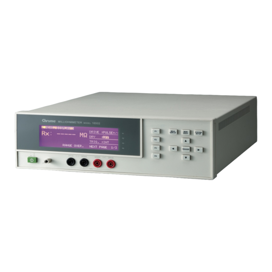
Description of Panel Description of Panel Front Panel (1) LCD Display The resolution of this instrument display is 240 x 64 dot-matrix LCD display, so all the measuring and setting values can be shown clearly. (2) Power Switch On-off switch (3) Unknown DUT Sockets Four individual BNC sockets connect an external test device or wire for unknown testing. -
Page 22: Rear Panel
Milliohm Meter 16502 User’s Manual Note If the user wants to reserve test mode setting parameter after powered-off. The user can press System Setup Key on front panel under test screen as well as press Meas Display Key then returns to test screen. After the above steps are completed, please turn off the unit. -
Page 23: Setting For Operation
Description of Panel (3) Power Voltage Switch Ensure power is off, then use screwdriver to switch to required voltage. (4) IEEE-488 INTERFACE Socket (Option) According to IEEE488-1978 standard input/output cord. The functions are: total remote control, output selection result, with or without controller, receives IEEE-488 interface connection line. - Page 24 Milliohm Meter 16502 User’s Manual < S Y S T E M S E T U P > C A L B R A T I O N ← Enter System Calibration Screen M E M M A N A G E ←...
- Page 25 Description of Panel KEY LOCK: It locks the key. The default setting is OFF. Switch to MEASURE DISPLAY or BIN COUNT or COMPARE COUNT the word <LOCK> will appear at upper right of test screen when it is on. To disable it, press [F1], [F4], and [SYSTEM SETUP]. CONTRAST: LCD contrast adjustment range is 0 ∼...
-
Page 26: Memory Manage
Milliohm Meter 16502 User’s Manual The default setting is 19200. CORREC.TEMP It sets the specified temperature value t0 (°C) that you want to convert in temperature correction function. The default setting is +20.0°C. THERM.COEFF It sets the coefficient αt0 in temperature correction function. The default setting is 3930 ppm. -
Page 27: Operation Instruction
4 / 4 Notices: The 16502’s panel displays the resistance value dividing into two kinds of RX and RTC. Among these two, RX is only for measuring resistance value and it won’t be affected by the temperature measurement result. RTC represents the instrument being with the... - Page 28 Milliohm Meter 16502 User’s Manual will be influenced by the temperature measurement result. Therefore, if you only measure the resistance value please be sure TEMP.: (F3) is OFF as well as panel display is RX. 2. Parameters settings are as following descriptions: DRIVE: Test mode setting, please see section 4.5 Reference Data for Operation.
-
Page 29: Compare Setting
Description of Panel BINNING: Binning setting. Press [F2] to switch OFF/ON. If setting is “ON” it will show “BIN X” word under measurement screen. This parameter is set under MAIN INDEX menu. TEMP.: It includes the functions of temperature measurement and correction. There are three types of selections OFF, AUTO and +20°C. -
Page 30: Binning Setting
Milliohm Meter 16502 User’s Manual to operate: (1) Press [F4], set MODE to percentage (%). (2) Press [F3] to move the cursor to NOMINAL position, and move the cursor to hundred then press [F1] key to adjust the number to 1. Press [F3] key to move the cursor to (-) position, then press [F1] key to set unit to m. - Page 31 Description of Panel < M A I N I N D E X : B I N N I N G > ← Condition setting S E T T I N G ← Counter C O U N T Press [F1] to enter setting screen as below shown: <...
-
Page 32: Reference Data For Operating
Milliohm Meter 16502 User’s Manual < B I N N I N G S E T > B I N D I G I T - - - - - - - - - - - - - - - - - - - - - - - - - - - - - - + 0 0 1 . - Page 33 EMFs will affect the measurement result. Vemf = Thermoelectric EMFs 16502 includes pulse mode selections of PULSE+, PLUSE- and PLUSE±. These modes are for avoiding the influence of thermoelectric so that applicable to temperature feature analysis of low resistance measurement and metallic conduction.
-
Page 35: Descriptions Of Gpib Interface (Commands Same As Rs232 Interface)
Descriptions of GPIB Interface (Commands Same as RS232 Interface) Overview The meter 16502 can be controlled remotely and is able to perform data transfer function via the IEEE-488.2/RS232 interface. Specification of IEEE-488 Interface For IEEE-488 interface, it is able to use the commands of 488.1 (compatible with KEITHIEY 5802) and 488.2 interfaces (including common and general commands.) It... -
Page 36: Ieee-488 Interface Connector
Milliohm Meter 16502 User’s Manual 5.2.4 IEEE-488 Interface Connector • Below shows the connector pin assignment: 1 DIO1 13 DIO5 2 DIO2 14 DIO6 3 DIO3 15 DIO7 4 DIO4 16 DIO8 5 EOI 17 REN 6 DAV 18 GND... -
Page 37: Port Driver
Descriptions of GPIB Interface (Commands Same as RS232 Interface) 5.2.6 Port Driver The specification of port driver is listed below: DIO1-8 Open Collector NRFD NDAC 3 States 5.2.7 Response of Interface Message Interface Message Meaning Response Be able to switch the instrument to Go To Local Local state Selective Device Clear... - Page 38 Milliohm Meter 16502 User’s Manual : CLEAr [No query] : RESUlt? [For query only] <NR1> : MATH : EXPRession : CATalog? [For query only] <NR3> : NAME DEV|PCNT DEV|PCNT : STATe <Boolean> <NR1> : LIMit : STATe <Boolean> <NR1> : NOMInal <NRf+>...
-
Page 39: Description Of Command Structure
Descriptions of GPIB Interface (Commands Same as RS232 Interface) SENSe : AVERage : COUNT <NR1> <NR1> : ZERO : STATe <Boolean> <NR1> : DATA? [For query only] <NR3> : RANG <NR1> | MIN | MAX} <NR1> : AUTO <Boolean> <NR1> MAX | VFAST | FAST | MAX | V.FAST | FAST | : SPEEd... - Page 40 Milliohm Meter 16502 User’s Manual In addition, to give two commands at the same time (ex. to set or query ZERO ON and OFFSet), use the following method to simplify the command. :SENSe:ZERO:STATe ON;DATA? It is same as the following two commands below, but simpler.
-
Page 41: Command Description
Descriptions of GPIB Interface (Commands Same as RS232 Interface) (3) <NR3> format: Ex.: 9.0E+3 <digit> <digit> <digit> 5.3.3 Command Description ABORt Command Command: ABORt Parameter: None Return: None Function: It aborts the measurement in executing immediately. CALCulate Command Set (1) Command: CALCulate: ALARm:CONDition { FAIL | PASS} Function: It defines the alarm output. - Page 42 Milliohm Meter 16502 User’s Manual Return: The query returns DEV or PCNT. (6) Command: CALCulate:BINNing: BIN(1~8): UPPer <NRf+> {Suffix Unit} Function: It sets or queries the high limit of BIN. Parameter: <NRf> | MINimum | MAXimum parameter is acceptable. DEV parameter range: 0.0000 MOHM(MIN) ∼ 200.0000 MAOHM(MAX).
- Page 43 Descriptions of GPIB Interface (Commands Same as RS232 Interface) Function: It returns numeric value after mathematics by setting (CALCulate: COMPare:MATH: EXPRession:NAME) Parameter: None Return: The query returns <NR3>. (13) Command: CALCulate:COMPare:MATH: EXPRession: NAME { DEV|PCNT} Function: It sets or queries the expression of numeric value. Parameter: DEV The expression of numeric value is absolute value.
- Page 44 Parameter: OFF means temperature correction doesn’t be executed under correction function as well as the current ambient temperature equals to the initial temp. setting under conversion function. AUTO means measuring the current ambient temperature by 16502 optional tester. (If there is no optional device, thus AUTO mode is disabled.) MAN means inputting the current ambient temperature by users.
- Page 45 Descriptions of GPIB Interface (Commands Same as RS232 Interface) Function: It sets or queries the coefficient of temperature conversion function. Parameter: <NR2> | MINimum | MAXimum parameter is acceptable. Range: 0.0(MIN) ~99.9(MAX) Return: The query returns <NR2>. (7) Command: TEMPerature:CORRect <NRf+> Function: It sets or queries the reference temperature of correction function.
- Page 46 Milliohm Meter 16502 User’s Manual PERCENT parameter range: 0.00(MIN) ~ 999.99(MAX). Unit: The units of parameter can be set to {MOHM | OHM | KOHM | MAOHM} when RSCAN:LIMit:STEP:MATH:NAME is set to DEV. If there is no giving unit, OHM will be defined automatically.
- Page 47 Descriptions of GPIB Interface (Commands Same as RS232 Interface) Parameter: None Return: The query returns <NR1>. 0, 9, 10, 11. 0 measurement result is LO. 9 measurement result is HI. 10 measurement result is GO. 11 is in STBY status not process measurement. (10) Command: RSCAN:MEASure:BL? Function: It queries BL value.
- Page 48 Milliohm Meter 16502 User’s Manual Return: The query returns <NR1> 0 or 1. (6) Command: SENSe:SPEEd { MAX|VFAST|FAST|MEDIum | SLOW} Function: It sets or queries the measurement speed. Parameter: MAX The measurement speed is maximum speed. VFAST The measurement speed is very fast.
- Page 49 Parameter: <NR2> 0.000S ∼ 100.0S Return: The query returns <NR3>. (4) Command: SYSTem:LFRequency {50 | 60} Function: It sets or queries the operating frequency of 16502. Parameter: 50 indicates the frequency is 50Hz. 60 indicates the frequency is 60Hz. Return: The query returns 50 or 60.
- Page 50 Parameter: <NR1> 0 ~ 15 Return: The query returns a numeric value in the format NR1. (7) Command: SYSTem:KLOCk {ON(1)|OFF(0)} Function: It sets or queries if the key of 16502 is locked. Parameter: {ON(1)|OFF(0)} Return: The query returns <NR1> 0 or 1.
- Page 51 COMP. DISP Saved EEPROM value PADR OFFSET Saved EEPROM 0.0 mΩ 0.0 mΩ value (9) Command: SYSTem: ERRor? Function: It queries the error number or message in the error queue of 16502. Parameter: None Return: numeric_value The error message number. 5-17...
- Page 52 Milliohm Meter 16502 User’s Manual string The error message string containing 80 characters max. (10) Command: SYSTem:LOCal Function: It releases 16502 REMOTE status. Parameter: None Return: None (11) Command: SYSTem:PADR[:OFFSet] <NRf+> Function: It sets or queries PADR OFFSET, the unit is in MOHM.
-
Page 53: Common Use Commands
CPLD EEPROM HANDLER Calibration Data *OPC It informs the 16502 to set the event register to OPC bit (bit 0) when the operation command is done. *OPC? It returns 1 when all operations and queries are done. *CLS It clears status data and the execution as described below. - Page 54 COMPARE Function Parmeter, the saved position is defined by numeric_value. BIN SORT Function Parmeter, the saved position is defined by numeric_value. TEMPERATURE CONVERSION Parameter RSCAN Parameter *TRG It triggers the 16502 in bus trigger mode as well as returns the measurement value after measured. 5-20...
-
Page 55: Status Reporting Structure
The 16502 Milliohm Meter can send an SRQ (Service Request) control signal when it requires the controller to perform a task. When the 16502 generates an SRQ, it also sets Bit 6 of the Status Byte Register, SRQ (Service Request) bit. Service Request Enable Register allows an operation programmer to select which summary messages in the Status Byte Register may cause service requests. -
Page 56: Status Byte Register
Operation Status Register Summary Bit Request Service Bit. This bit is set when any enabled bit of the Status Byte Register has been set, which indicates 16502 has at least one reason for requesting service. Standard Event Status Register Summary Bit. -
Page 57: Standard Event Status Register
Descriptions of GPIB Interface (Commands Same as RS232 Interface) Standard Event Status Register The Standard Event Status Register is frequently used and is one of the simplest. The common use commands *ESE and *ESR? can by utilized to program it. Summary Message Event Read Standard... -
Page 58: Operating Status Group
Bit No Bit Weight Description 6-15 Always 0. This bit is set to 1 when the 16502 can accept a trigger. This bit is set to 1 when the 16502 is actively measuring. Always 0. Always 0. Always 0. Always 0. -
Page 59: Rs-232C Signal Line And Pin Assignment
Descriptions of GPIB Interface (Commands Same as RS232 Interface) RS-232C Signal Line and Pin Assignment Name Description Ground Ground wire /TxD Transmitting data Data /RxD Receiving data 5-25... -
Page 61: Description Of Zero Correction
Description of ZERO Correction Description of ZERO Correction 1. Power on the instrument after all are normal, enter main index as the below screen shown. < M E A S . D I S P L A Y > ← Select test mode D R I V E : P U L S E + /-... -
Page 63: Description Of Handler Interface
Description of Handler Interface Description of Handler Interface BINNING and COMPARE in 16502 are all connected to external unit by Handler interface. The connectors are 24 Pin, pin descriptions are as following. Description of Handler Interface Pins for BINNING Name... -
Page 64: Description Of Handler Interface Pins For Compare
Milliohm Meter 16502 User’s Manual Description of Handler Interface Pins for COMPARE Name Description /EXT Triggered externally 3,20 /FAIL LO Primary parameter test value of Rx too low 4,24 /FAIL HI Primary parameter test value of Rx too high Ground... -
Page 65: Descriptions Of Temperature Measurement And Correction Function
The standard measurement probe is PT100 type of platinum temperature sensor and it is 1.5m in length. The probe head is capable of measuring -50°C ~ 300°C. Plug the connector of end into the port of TC SENSOR on the rear panel of 16502. The temperature measurement probe is as below shown. -
Page 66: Operation For Temperature Measurement
Milliohm Meter 16502 User’s Manual A165015 temperature probe Operation for Temperature Measurement Temperature measurement function calculates the value of unknown temperature by the condition of known temperature and resistance values. It is often used to calculate the change of transformer or motor coil. -
Page 67: Description For Setting Menu
CONSTANT : Resistance value is temperature constant of zero. (Copper: 235; Aluminum: 230) Setting procedure: (1) Press [MAIN INDEX] after 16502 powered-on, thus the following screen will be shown. < M A I N I N D E X >... -
Page 68: Description For Operating Menu
DIGIT UP [F1] to increase the digit along with DIGIT DOWN [F2] to decrease the digit. 8.2.3 Description for Operating Menu 1. Press [MAIN INDEX] after 16502 powered-on then press TEMP.CONV. [F3], thus the following screen will be shown. <... - Page 69 Descriptions of Temperature Measurement and Correction Function T mode display screen: < T E M P . C O N V . M E A S . > R A N G E : A 2 0 0 m Ω R x : 0 .
-
Page 70: Operation Example
Milliohm Meter 16502 User’s Manual < T E M P . C O N V . M E A S . > R A N G E : A 2 0 0 m Ω R x : 0 . 0 1 mΩ... -
Page 71: Description For Temp. Correction Function
Descriptions of Temperature Measurement and Correction Function Description for Temp. Correction Function Temp. correction function is mainly by using the resistance value of known specific temperature(for instance, 30°C is 100Ω) of lead(ex. copper, aluminum wire) as well as known temp. coefficient (ex. 3930PPM) to infer the other resistance value when temp. is 20°C. 1. -
Page 72: Operating Description
Milliohm Meter 16502 User’s Manual 2. Press [F3] (i.e. SYSTEM CONFIG) key to enter System Config Screen as below figure. < S Y S T E M C O N F I G > D I G I T A V E R A G E N O . - Page 73 Descriptions of Temperature Measurement and Correction Function < M E A S . D I S P L A Y > C O M P A R E : O F F 0 1 mΩ B I N N I N G : O F F ←...
-
Page 74: Operation Example
Milliohm Meter 16502 User’s Manual however [] and [] are for fine adjustment. The panel of 16502 shows R a resistance value after converted under this selection. 8.3.3 Operation Example In the above section example, the ambient temp. is 30°C, meanwhile the resistance value of measured copper wire is 100Ω. -
Page 75: R Scan Function
R SCANNER. R Scan Interface R SCAN interface is for an R SCANNER installed on output terminal of 16502 front panel. It is connected and controlled with the 16502 via D-SUB 9Pin changing to Handler control line. -
Page 76: R Scanner Specification
To transmit /EXT, PASS and FAIL signals by using Handler interface to connect with User Automatic Machine. The output signals of D-, S-, D+ and S+ in the 16502 Millohm Meter can be connected to the pins set for measuring the setting equivalent resistance through R Scanner. -
Page 77: Operation For R Scan
Press F1 to increase digit, F2 to decrease digit, F3 to select adjusted digit and F4 to select high/low limit mode. There are three groups of DCR in 16502 R SCAN function for test and pin variation. The setting method is as the table below. The Default is for setting three groups of DCRs. The extra DCR set to 0-0 via F1, F2 and F3 when these three groups of setting not to be used. -
Page 78: Test Description For R Scan
Press [F4] to change the setting under this screen. AUTO function is for temperature auto measuring which shows the measurement in currently temperature. AUTO function won’t be showed when 16502 temperature card doesn’t be inserted. Furthermore +20°C temperature value inputted by manual, the numeric isn’t 20 definitely but just an example. - Page 79 R SCAN Function R SCAN Connection Diagram Pin list: Handler interface of 16502 D-sub 9 pin of R scanner Handler 24 pin of ATS (Connector A) test fixture (Connector B) (Connector C) /EXT /EXT P04,P24 RESERVE RESERVE P08 GND COMMON...
- Page 81 Chroma’s Continuous Quality Process User Manual Customer Feedback Chroma welcomes all comments and recommendations to improve this publication in the future editions. Please scan the QR code below or click the URL http://www.chromaate.com/survey?n=793ce6db-17ef-4cd3-b0de-8bbd09aa38e0 to fill in the customer feedback form. Thank you!
- Page 82 66 Huaya 1st Road, Guishan, Taoyuan 33383, Taiwan 台灣桃園市 33383 龜山區 華亞一路 66 號 T +886-3-327-9999 F +886-3-327-8898 Mail: info@chromaate.com http://www.chromaate.com Copyright by CHROMA ATE INC. All Rights Reserved. All other trade names referenced are the properties of their respective companies.
Need help?
Do you have a question about the 16502 and is the answer not in the manual?
Questions and answers