Table of Contents
Advertisement
Quick Links
Advertisement
Table of Contents

Related Manuals for Chroma 66203


Summary of Contents for Chroma 66203
- Page 1 Digital Power Meter 66203/66204 User’s Manual...
- Page 3 Digital Power Meter 66203/66204 User’s Manual Version 1.0 March 2014...
- Page 4 The information in this document is subject to change without notice. Chroma ATE INC. makes no warranty of any kind with regard to this manual, including, but not limited to, the implied warranties of merchantability and fitness for a particular purpose.
- Page 5 Chroma’s obligation under this warranty is limited solely to repairing any such instrument, which in Chroma’s sole opinion proves to be defective within the scope of the warranty when returned to the factory or to an authorized service center. Purchaser is responsible for the shipping and cost of the service item to Chroma factory or service center.
- Page 6 Material Contents Declaration The recycling label shown on the product indicates the Hazardous Substances contained in the product as the table listed below. : See <Table 1>. : See <Table 2>. <Table 1> Hazardous Substances Lead Mercury Cadmium Hexavalent Polybrominated Polybromodiphenyl Part Name Chromium...
- Page 7 “ ” indicates that the level of the specified chemical substance exceeds the threshold level specified in the standards of SJ/T-11363-2006 and EU 2005/618/EC. Chroma is not fully transitioned to lead-free solder assembly at this moment; however, most of the components used are RoHS compliant.
- Page 9 Failure to comply with these precautions or specific WARNINGS given elsewhere in this manual will violate safety standards of design, manufacture, and intended use of the instrument. Chroma assumes no liability for the customer’s failure to comply with these requirements.
- Page 10 Safety Symbols DANGER – High voltage. Explanation: To avoid injury, death of personnel, or damage to the instrument, the operator must refer to an explanation in the instruction manual. High temperature: This symbol indicates the temperature is now higher than the acceptable range of human. Do not touch it to avoid any personal injury.
- Page 11 Revision History The following lists the additions, deletions and modifications in this manual at each revision. Date Version Revised Sections Mar. 2014 Complete this manual.
-
Page 13: Table Of Contents
Digital Power Meter 66203/66204 User’s Manual Table of Contents Overview.......................1-1 Introduction......................1-1 Initial Inspection.....................1-1 Ambient Environment ....................1-2 Power Line Connection ..................1-2 Fuse........................1-3 Time for Warm-Up ....................1-4 Cleaning ........................1-4 Specification ......................2-1 Standard Specification...................2-1 Common Specification...................2-3 Panel Description ....................3-1 Front Panel ......................3-1 Rear Panel......................3-3 Operation......................4-1... - Page 14 Digital Power Meter 66203/66204 User’s Manual 5.5.3 Program Message ..................5-5 5.5.4 Response Message ..................5-5 Traversal of the Command Tree................5-6 The Commands of the Power Meter..............5-8 5.7.1 Standard Commands ..................5-8 5.7.2 Instrument Commands ................5-11 Status Reporting....................6-1 Introduction......................6-1 Register Information in Common ................6-1 6.2.1...
-
Page 15: Overview
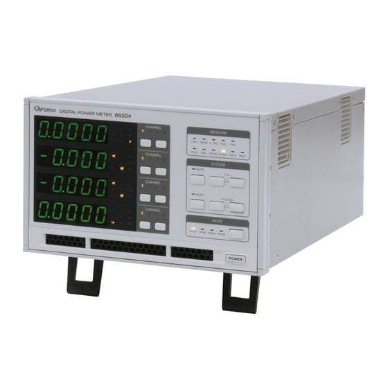
Overview Introduction This manual covers the 66203 and 66204 Digital Power Meters that have 3 and 4 channels respectively to test multiple UUTs at the same time reducing the testing time and improving the productivity. The Digital Power Meter can also test the products with 3-phase power system through the test parameters of voltage, current, power and power factor. -
Page 16: Ambient Environment
Digital Power Meter 66203/66204 User’s Manual Ambient Environment Do not use the meter in a dusty or vibrating Keep away fro m the fo llow ings: location. Do not expose it to sunlight or corrosive gas. Be sure that the ambient Du st temperature is 0°C ~ +40°C and the relative... -
Page 17: Fuse
Overview AC INPUT Power Specification Figure 1-1 AC INPUT Power Spec. Label Fuse The meter has one fuse installed on the rear panel. Please be aware of the following when replacing it: (1) Be sure to turn off the power and unplug the power cord before changing the fuse. (2) Since visual check cannot make sure the fuse to be used is appropriate, it is necessary to test its resistance to see if it is below 2Ω... -
Page 18: Time For Warm-Up
Digital Power Meter 66203/66204 User’s Manual Time for Warm-Up All functions of this meter are active when it is powered on; however, to meet the accuracy listed in the specification it is suggested to warm-up for at least 30 minutes. -
Page 19: Specification
Specification Specification Standard Specification Functions Model 66203 66204 Channel 3 Channel 4 Channel Measurement Vrms, Vpk+, Vpk-, VTHD, Irms, Ipk+, Ipk-, ATHD, Is, CFi, W, VA, Parameters VAR, PF, F, Energy Input Measurement Ranges Voltage 15V/30V/60V/150V/300V/600V/Auto Measurement The crest factor of all measurement ranges is 2. - Page 20 Digital Power Meter 66203/66204 User’s Manual Accuracy Requirements Temperature: 23°C±5°C Humidity: 80%RH. Input waveform: Sine wave Power factor: 1. Warm-up time: ≧30 minutes. Connect the power cord to a three-prong power outlet with proper grounding. Voltage / Harmonics Specifications DC, 10Hz-1kHz...
-
Page 21: Common Specification
Safety & EMC CE (include EMC & LVD) 419 x 210 x 132 mm / 16.50 x 8.27 x 5.20 inch Dimension (W×H×D) (excluding projections) 8.5 kg / 18.72 lbs (Model 66204) Weight 7.8 kg / 17.18 lbs (Model 66203) -
Page 23: Panel Description
Panel Description Panel Description Front Panel The front panel of 66203/66204 Digital Power Meter is as Figure 3-1 shows and the functions numbered from 1 to 10 are described below. Figure 3-1 Front Panel of 66204 Digital Power Meter Function menu setup &... - Page 24 Digital Power Meter 66203/66204 User’s Manual SETUP, TRIG/ENTER & : The SETUP key is able to select the function menu and set SYSTEM the functions in it. The TRIG/ENTER key is to confirm the selection of function and measurement range, also to trigger the Energy, Is and limit for GO/NG.
-
Page 25: Rear Panel
Panel Description Rear Panel The rear panel of 66203/66204 Digital Power Meter is as Figure 3-2 shows and the functions numbered from 1 to 7 are described below. Figure 3-2 Rear Panel of 66204 Digital Power Meter Voltage measurement : It is the DC/AC voltage signal input terminal. The input terminal maximum input voltage is 600Vrms. -
Page 27: Operation
Operation Operation Preparation for Test (1) Check the input range of power voltage on the rear panel and make sure the power switch is OFF before plugging in the power cord. (2) Make sure the fuse used is applicable. See the section of 1.5 Fuse for the specification required. -
Page 28: Setting Gpib Address, Display Backlight & Sound
Digital Power Meter 66203/66204 User’s Manual Figure 4-2 Process for Checking Firmware & Digital Version 4.2.2 Setting GPIB Address, Display Backlight & Sound Figure 4-3 Menu for Setting Communication Address, Display Backlight & Sound After the power-on self-test is done, press SETUP and TRIG/ENTER at the same time to enter into the system menu. -
Page 29: Storing & Recalling Setting File
Since the measurement function and parameter setting on the multi-channel power meter is much more complicate than the single channel power meter, the 66203/66204 Digital Power Meter provides 10 groups of settings for storing and recalling to facilitate the usage. -
Page 30: Connecting Test Device
Digital Power Meter 66203/66204 User’s Manual Figure 4-6 Process for Saving & Recalling Setting File Connecting Test Device 4.3.1 Standard Connection The connection of every channel on the single phase or multi-phase (3-phase) of power meter can select the following two ways. The measurement theory is shown in Figure 4-7 as the diagram (a) and (b) shows. -
Page 31: Efficiency Test For Ac Motor Driver
4.7 for wiring mode. Figure 4-8 Power Meter Configuration for Testing Motor Driver’s Efficiency output power × × Efficiency input power Wiring for testing 66204: Figure 4-9 Wiring Diagram of 66203/66204 & Motor Driver for Efficiency Test... - Page 32 Digital Power Meter 66203/66204 User’s Manual Wiring for motor driver primary side (input side) Figure 4-10 Input Wiring of 66203/66204 & Motor Driver for Efficiency Test Wiring for motor driver secondary side (output side) Figure 4-11 Output Wiring of 66203/66204 & Motor Driver for Efficiency Test...
- Page 33 Operation Use I RANGE key to select an appropriate current range for each channel to conduct testing. Figure 4-13 Process for Setting Current Range After confirmed all wirings are correct, secured and safe, turn on the motor driver and start the driver to control the motor. Set the wiring mode of the 66204 to 3P3W.
- Page 34 Digital Power Meter 66203/66204 User’s Manual Figure 4-15 Test Value of Motor Driver Input Side To display the measurement of motor driver secondary side (output side): Press the FUNC key of display 1~display 4 to set the indicator measurement parameter to V, A, W, PF respectively, and then press the CHSEL of display 1~display 4 to set the channel to 1 or 2 for respective check.
-
Page 35: Computing Equation For Measurement Parameters
Thus, it is the true power factor. Besides the measurement of rms value, the 66203/66204 Digital Power Meter also has DC measurement. If the input voltage and current waveform has AC and DC portion, the period average of AC waveform is able to get the average value of voltage and current while the power is the product of average voltage and average current. - Page 36 Digital Power Meter 66203/66204 User’s Manual The frequency measurement detects the input voltage signal frequency. It is a computed average value after captured the input voltage signal within a time interval. The measured voltage frequency can also be the base of current measurement time.
- Page 37 Operation Crest Factor imum − THD & Harmonic value ..× the subscript n indicates the range of harmonic which is 2.3.4….100..× the subscript n indicates the range of harmonic which is 2.3.4….100. Integration Energy (Wh or Joule) ∫...
-
Page 38: Setting Measurement Range
The 66203/66204 will not provide the measurement at this time. Figure 4-17 Range Selection Rule Under the 66203/66204 allowed rated power, to keep the protection mechanism from being too sensitive, the OCR or OCP warning message will occur after confirmed the signal peak is over the protection limit for 0.5 seconds. -
Page 39: Setting Voltage Range
4.5.1 Setting Voltage Range Figure 4-18 Voltage Range Setup Screen The 66203/66204 Digital Power Meter has 6 ranges for voltage measurement, which are 600Vrms/300Vrms/150Vrms/60Vrms/ 30Vrms/15Vrms and the crest factor (CF) of each range is 2. Thus, the measureable range for voltage peak is ± (range×CF). -
Page 40: Setting Current Range
Digital Power Meter 66203/66204 User’s Manual Figure 4-20 Process for Setting Voltage Range If any of the channel’s voltage range is set to Manual, the AUTO indicator will not be on. In other word, the AUTO indicator only turns on when all the voltage range of all channels are set to AUTO. - Page 41 Operation The 66203/66204 Digital Power Meter has 8 ranges for current measurement, which are 20Arms/5Arms/2Arms/0.5Arms/0.2Arms/ 0.05Arms/0.02Arms/0.005Arms and the crest factor (CF) of each range is 4. Thus, the measureable range for current peak is ± (range×CF). When using Manual range or Auto range in 20A (high shunt range) or 0.2A (Low shunt range), if the input current peak is four times over the range, the display will show Over Current Range (OCR) warning message and beep.
- Page 42 Digital Power Meter 66203/66204 User’s Manual Figure 4-24 Process for Setting Current Range If Shunt is set to Low, the current has only 4 ranges for selection which are 0.2Arms/0.05Arms/0.02Arms/0.005Arms. If Shunt is set High, it also has 4 ranges for selection which are 20Arms/5Arms/ 2Arms/0.5Arms.
-
Page 43: Setting External Range
4.5.3 Setting External Range Figure 4-25 External Range Setup Screen The 66203/66204 Digital Power Meter has 4 ranges for external measurement, which are 100mVrms/50mVrms/25mVrms/10mVrms and the crest factor (CF) of each range is 4. Thus, the measureable range for current peak is range×CF. -
Page 44: Setting Measurement Functions
Digital Power Meter 66203/66204 User’s Manual Figure 4-27 Process for Setting Current Range External If any of the channel’s external range is set to Manual, the AUTO indicator will not be on. In other words, the AUTO indicator is on only when the external range of all channels is set to AUTO. -
Page 45: Limit
Operation 4.6.1 Limit Figure 4-28 Limit Function Setup Screen Enable the Limit function by setting the detection time and the upper/lower limits of each parameter can judge if the measured data is within the specification. The parameters include V, Vpk+, Vpk-, I, Ipk+, Ipk-, Is, W, PF, VA, VAR, CFi, VTHD, ATHD, E and F. The user can select one or several of them for setting. - Page 46 Digital Power Meter 66203/66204 User’s Manual Figure 4-29 Procedure for Setting Limit Function The figure below shows the rule for judging the measured value comparing to the upper/lower. Figure 4-30 GO/NG Upper Limit Comparison Rule Figure 4-31 GO/NG Lower Limit Comparison Rule...
- Page 47 The upper and lower limits of every test parameter are different. If the upper and lower limits are set to “- - - - -”, it means no setting. The 66203/66204 Digital Power Meter has 3 parameters that require pressing TRIG/ENTER for triggering. They are E (energy), Is (Inrush current) and GO/NG.
-
Page 48: Meas
Digital Power Meter 66203/66204 User’s Manual 4.6.2 Meas The Meas menu of the 66203/66204 Digital Power Meter has Shunt, Meas, Integ, Filt, Disp, Hold, THD, Inrush, Energy, CT, ExtenSH, HV, EFF total 13 functions that are described below. SHUNT Figure 4-34 Setup Screen of SHUNT The 66203/66204 Digital Power Meter offers two internal shunts for current sensing which are 5mΩ... - Page 49 MEAS Figure 4-36 WINDOW Measurement Setup Screen The 66203/66204 Digital Power Meter provides two average methods to calculate the measured values. They are Windo (window) and Avg (average). The major differences of them are sampling and calculation as described below.
- Page 50 The window time range available for the 66203/66204 Digital Power Meter is 0.1 sec. ~ 60 sec. with the resolution set to 0.1 sec. The default is 4 seconds.
- Page 51 Operation Figure 4-38 Process for Setting WINDOW & AVG Measurement Functions ■ If the UUT voltage or current is unstable, using the Moving Average Method can get a stable measured value. The more average number of times, the measured value is more stable.
- Page 52 Digital Power Meter 66203/66204 User’s Manual INTEG Figure 4-39 INTERGRATION Setup Screen The 66203/66204 Digital Power Meter is able to use energy accumulation to measure the UUT power, voltage and current RMS within the fixed time consecutively in INTEGRATION mode.
- Page 53 Operation Use ↑, ↓ to select intEG in the 1 display window and press TRIG/ENTER to confirm it. Use ↑, ↓ to select ON or OFF in the 2 display window to enable or disable integration and press TRIG/ENTER to confirm the selection. Use ↑, ↓...
- Page 54 FILT Figure 4-42 FILTER Setup Screen The 66203/66204 Digital Power Meter has low pass digital filter function with 5 kHz cutoff frequency that is compliant with the IEC 61000-3-2 international standard. When the filter is enabled, it can filter out the high frequency noise from the input voltage and current signal such as the switch noise of switchable power supply.
- Page 55 DISP Figure 4-45 DISPLAY Refresh Rate Setup Screen The 66203/66204 Digital Power Meter is able to adjust the display refresh rate for the measured value. The rates for adjustment are 0.25, 0.5, 1.0 and 2.0 (unit: second). The default setting is 0.5 second. The display refresh rate can be increased if the signal under test turns faster.
- Page 56 HOLD Figure 4-47 HOLD Setup Screen The 66203/66204 Digital Power Meter has hold function that is triggered by Stop, Max and Min three kinds of conditions. The measured values can be hold are V, Vpk+, Vpk-, A, Apk+, Apk-, W, VA, VAR, PF, F, Cfi, VTHD, ATHD, EFF, Vdc, Idc and Pdc.
- Page 57 Max. Figure 4-49 THD Setup Screen The Total Harmonic Distortion (THD) function of the 66203/66204 Digital Power Meter is to calculate the RMS ratio from the higher order harmonics and the fundamental. Please see section 4.4 for the THD calculation formula. The power meter uses the internal zero-crossing circuit and frequency calculation module to get the fundamental wave frequency.
- Page 58 6 kHz signal of the harmonic will be filtered out; therefore, it is necessary to evaluate the influence caused by the filter. The 66203/66204 Digital Power Meter is unable to show the composition of harmonic but VTHD or ATHD only. However, it can view the fundamental, harmonic and DC composition via the software panel.
- Page 59 The measured current often requires to cross several current ranges of the 66203/66204 power meter. If the range is set to auto, the best measurement time may be missed when switching the range. Thus, range change is not allowed when doing inrush current measurement.
- Page 60 Digital Power Meter 66203/66204 User’s Manual Last, the 2 display window shows level, use ↑, ↓ to set the trigger level in the 3 display window with the level unit of Ampere and press TRIG/ENTER to return to the main menu of 1 display window.
- Page 61 ENERG Figure 4-54 ENERGY Setup Screen The 66203/66204 Digital Power Meter is able to measure the UUT’s energy within a period of time. The energy units for selection are Joule and WHr. The calculation of energy is the integration of active power to time. Changing the voltage or current range within the...
- Page 62 The range change can only be accepted when the measurement is stopped. When the UUT’s voltage or current peak exceeds the measurement range upper limit, the 66203/66204 will prompt a warning message and stop measuring. However, it will not prompt an error message and stop the measurement if the signal peak is temporary.
- Page 63 Figure 4-56 CT Setup Screen If the UUT’s maximum current exceeds the maximum range of the 66203/66204 Digital Power Meter, the Current Transducer (CT) can be selected to work with the power meter.
- Page 64 If CT is not used for current measurement, the CT function should be turned off to avoid wrong calculation. The internal shunt of the 66203/66204 is the load of CT secondary side. The shunt resistance is 5mΩ (High shunt) and 500mΩ (Low shunt) respectively.
- Page 65 ExtSH Figure 4-60 EXTERNAL Setup Screen If the maximum current of UUT exceeds the maximum range of the 66203/66204 Digital Power Meter, it can select external shunt to work with the power meter for measurement. It would need to enable the ExtSH function on the power meter and set the external shunt resistance.
- Page 66 When done, press SETUP to exit the menu. Figure 4-62 Process for Setting ExtSH The input impedance of the 66203/66204 EXT terminal is 100kΩ that could affect the equivalent impedance of external shunt and the measurement accuracy. Please use this function properly.
- Page 67 Measurement Kit can increase the range up to 1200V, but the frequency applicable range is limited to DC and 47Hz~63Hz. To ensure the measurement spec, the HV function of 66203/66204 can only work with the option A662012. Please see Appendix F for the specification of A662012.
- Page 68 Digital Power Meter 66203/66204 User’s Manual Following is the procedure to set the HV function: Press SETUP to select Meas. The Meas indicator is on. Use ↑, ↓ to select HV function in 1 display window and press TRIG/ENTER to confirm Use ↑, ↓...
- Page 69 Operation Figure 4-66 EFFICIENCY Setup Screen The 66203/66204 Digital Power Meter has EFF function to calculate the efficiency of power supply or energy converter. The EFF defines the calculation to be A/B or B/A. Please follow the table below the assign the measurement channel to A or B based on the set wiring mode.
- Page 70 Digital Power Meter 66203/66204 User’s Manual A & B Definition of EFF Function of 66204 WIRE MODE 1P2W 1P3W 3P3W 3P4W A & B Definition of EFF Function of 66203 WIRE MODE 1P2W 1P3W 3P3W 4.6.3 DC Figure 4-68 DC Measurement Setup Screen Please see section 4.4 for the calculation formula of DC value.
-
Page 71: Wiring Mode
Wiring Mode As the table shown below, the 66203/66204 Digital Power Meter provides 4 types of wiring modes for single and 3-phase power measurements. The actual wiring has to match the selected wiring mode and follow the table or wiring diagram below to select the correct channel for measurement;... -
Page 72: Selecting 1P3W Wiring Mode
Digital Power Meter 66203/66204 User’s Manual Figure 4-69 1P2W Wiring Diagram 4.7.2 Selecting 1P3W Wiring Mode Single phase 3-wire power is the most frequent seen application for residential electricity. The L1-L2 is for the household appliance with larger capacity and the L1-N and L2-N voltage is for the household appliance with smaller capacity in phase. - Page 73 Operation (3-phase 4-wire – using three-wattmeter method) − Based on Kirchhoff’s current law, . Thus, − − − − From the formula above, it can use two wattmeters to measure the power of 3 phases that is to use the wattmeter on channel 1 to measure the L1 current and the L1 to L3 v −...
- Page 74 Digital Power Meter 66203/66204 User’s Manual Figure 4-72 Three-Wattmeter Method Wiring 4.7.5 Selecting 3P4W Wiring Mode, Three-Wattmeter Method Taking the example of Y connection 3-phase power measurement, it uses 3 power meters to grab the individual instantaneous power of 3 phases simultaneously and calculate the average power of each phase and then sum up to get the total power.
-
Page 75: Fans Inspection
Figure 4-73 Three-Wattmeter Method Wiring Fans Inspection The 66203/66204 Digital Power Meter has two cooling fans which are located on the right side of the device at the front and the rear. The fan at the front runs after powered on to help dissipating the heat of internal circuit. -
Page 77: Using Remote Control
Using Remote Control Overview 66203/66204 provides GPIB and USB two kinds of remote control interfaces and all functions of panel keys can be controlled by these two interfaces. The USB interface supports USB 2.0 / USB 1.1, while the GPIB interface is complied with IEEE-488 standard. -
Page 78: The Gpib Capability Of The Power Meter
Digital Power Meter 66203/66204 User’s Manual The GPIB Capability of the Power Meter GPIB Capability Response Interface Functions Talker/Listener Commands and response messages can be sent AH1, SH1, T6, L4 and received over the GPIB bus. Status information can be read using a series poll. -
Page 79: Basic Definition
Using Remote Control Numerical Data Formats Chroma 66203/66204 Power Meter accepts the numerical data type listed in Table 5-1. Table 5-1 Numerical Data Type Symbol Description Example <NR1> It is a digit with no decimal point. The decimal is assumed to 123 , 0123 be at the right of the least significant digit. -
Page 80: Program Headers
Digital Power Meter 66203/66204 User’s Manual 5.5.2 Program Headers Program headers are key words that identify the command. They follow the syntax described in subsection 5.8 of IEEE 488.2. The Power meter accepts characters in both upper and lower case without distinguishing the difference. Program headers consist of two distinctive types, common command headers and instrument-controlled headers. -
Page 81: Program Message
Using Remote Control Instrument Commands, the upper case is part of short-form. For instance, SYSTem : ERRor? can be wrote as SYST : ERR? Program Header Separator ( : ): If a command has more than one header, the user must separate them with a colon (example: FETC:CURR:RMS? or POW:INT 10). -
Page 82: Traversal Of The Command Tree
Digital Power Meter 66203/66204 User’s Manual Query: FILT?;:COMP:LIM:V?;:COMP? Response: ON ; 220.0 , 50.0 ; OFF Response Message Unit Separator ( ; ): The separator (semicolon ;) separates the response message unit elements from one another in a response message. - Page 83 Using Remote Control TRIGger : STATe? All colons are header separators. : TRIGger : STATe? Only the first colon is a specific root. TRIGger : STATe? ; : VOLTage : RANGe V150 Only the second colon is a specific root. Header Data Message Terminator...
-
Page 84: The Commands Of The Power Meter
Digital Power Meter 66203/66204 User’s Manual The Commands of the Power Meter 5.7.1 Standard Commands *CLS Description: This command clears the status byte register and the event registers. Setting syntax: *CLS<PMT> Setting parameters: none Setting example: none Query syntax: none... - Page 85 Setting parameters: none Setting example: none Query syntax: *IDN?<PMT> Return parameters: <SRD>, “Manufacturer,Model name,Serial number,F/W version, FPGA version,PCB version” Information Example Manufacturer Chroma ATE Model name 66204 Serial number 66204A000066 F/W version 1.00 FPGA version 1.00 PCB version 1.00 Header on: <SRD><RMT>...
- Page 86 Digital Power Meter 66203/66204 User’s Manual MSS = master status summary MAV = message available CSUM = channel status summary Setting syntax: none Setting parameters: none Setting example: none Query syntax: *STB?<PMT> Return parameters: <NR1>, 0 ~ 255 Header on: <NR1><RMT>...
-
Page 87: Instrument Commands
Using Remote Control 5.7.2 Instrument Commands SYSTEM Sub-system SYSTem:ERRor? Description: This command queries the error string of the command parser. Setting syntax: none Setting parameters: none Setting example: none Query syntax: SYSTem:ERRor?<PMT> Return parameters: <SRD>, 0,“No Error” 1,“Data Format Error” 2,“Data Range Error”... - Page 88 Digital Power Meter 66203/66204 User’s Manual Setting example: none Query syntax: SYSTem:TRANsmit:TERMinator?<PMT> Return parameters: <NR1>, 0 ~ 1 Header on: :SYSTEM:TRANSMIT:TERMINATOR<space><NR1><RMT> Header off: <NR1><RMT> Query example: none SYSTem:VERsion? Description: This query returns an <NR2> formatted numeric value corresponding to the SCPI version number for which the instrument complies.
- Page 89 Using Remote Control Event register > 0, QUES bit of the Status Byte register is set too. Setting syntax: none Setting parameters: none Setting example: none Query syntax: STATus:QUEStionable?<PMT> Return parameters: <NR1>, 0 ~ 65535 Header on: :STATUS:QUESTIONABLE:EVENT<space><NR1><RMT> Header off: <NR1><RMT>...
- Page 90 Digital Power Meter 66203/66204 User’s Manual corresponding bit in the Questionable Event register. Bit Configuration of Questionable Status Register Bit position 14~6 Condition Energy Inrush Integrate : Over voltage range. : Over current range. : Over current protection. Integrate RCE : Range change error when integrate mode running.
- Page 91 Using Remote Control Return parameters: <NR1> Bit Configuration of Channel Status Register Bit position 15~6 Energy Inrush Integrate Condition Bit weight Query example: STAT:CHAN:COND? Return the status of the power meter. Return example: 2048 STATus:CHANnel:EVENt? Type: Channel-Specific. Description: Record all channel events that have occurred since last time the register was read, and reset the Channel Event register.
- Page 92 Digital Power Meter 66203/66204 User’s Manual STATus:CHANnel:NTRansition Type: Channel-Specific. Description: Programmable filters that determine 1-to-0 transition in the Condition register will set the corresponding bit of the Event register. Setting syntax: STATus:CHANnel:NTRansition<space><NR1><PMT> Setting parameters: <NR1>, 0 ~ 65535, Unit = None...
- Page 93 This query requests the module to identify itself. Setting syntax: none Setting parameters: none Query syntax: CHANnel:ID?<PMT> Return parameters: <SRD>, “Manufacturer,Model name,Serial number,F/W version, FPGA version,PCB version” Information Example Manufacturer Chroma ATE Model name 66204 Serial number 66204M000066 F/W version 1.00 FPGA version 1.00 PCB version 1.00 Header on: :CHANNEL:ID<space><SRD><RMT>...
- Page 94 Digital Power Meter 66203/66204 User’s Manual Header on: :FETCH<space>V<space><NR2>;VPK+<space><NR2>;VPK-<space>< NR2>;THDV<space><NR2>;I<space><NR2>;IPK+<space><NR2>;IPK-< space><NR2>;IS<space><NR2>;CFI<space><NR2>;THDI<space><NR 2>;W<space><NR2>;PF<space><NR2>;VA<space><NR2>;VAR<space ><NR2>;ENEG<space><NR2>;FREQ<space><NR2>;VDC<space><NR 2>;IDC<space><NR2>;WDC<space><NR2><RMT> Header off: <NR2>;<NR2>;<NR2>;<NR2>;<NR2>;<NR2>;<NR2>;<NR2>;<NR2>;<N R2>;NR2>;<NR2>;<NR2>;<NR2>;<NR2>;<NR2>;<NR2>;<NR2>;<NR2> <RMT> Separator 0: <NR2>,<NR2>,<NR2>,<NR2>,<NR2>,<NR2>,<NR2>,<NR2>,<NR2>,<N R2>,<NR2>,<NR2>,<NR2>,<NR2>,<NR2>,<NR2>,<NR2>,<NR2>,<NR2 ><RMT> Separator 1: <NR2>;<NR2>;<NR2>;<NR2>;<NR2>;<NR2>;<NR2>;<NR2>;<NR2>;<N R2>;<NR2>;<NR2>;<NR2>;<NR2>;<NR2>;<NR2>;<NR2>;<NR2>;<NR2 ><RMT> Example 2: Query: FETC?<space>V,I,W<PMT> Response: Header on: :FETCH<space>V<space><NR2>,I<space><NR2>,W<space><NR2><R MT> Header off: <NR2>,<NR2>,<NR2><RMT>...
- Page 95 Using Remote Control :FETCH:VOLTAGE:RMS<space><NR2>,<NR2>,<NR2>,<NR2><R MT> Header off: <NR2><RMT> <NR2>,<NR2>,<NR2>,<NR2><RMT> Example: none FETCh[:SCALar]:VOLTage:PEAK+? {<NR1>} MEASure[:SCALar]:VOLTage:PEAK+? {<NR1>} Type: Channel-Specific. Description: These queries return the plus value of peak voltage. The return could be -3 or <NR2>. -3: Invalid data when OVR occur. Setting syntax: none Setting parameters: none...
- Page 96 Digital Power Meter 66203/66204 User’s Manual -3: Invalid data when OVR occur. Setting syntax: none Setting parameters: none Query syntax: FETCh:VOLTage:DC?<PMT>, FETCh:VOLTage:DC?<space><NR1><PMT>, MEASure:VOLTage:DC?<PMT>, MEASure:VOLTage:DC?<space><NR1><PMT> Query parameters: <NR1>, 0 ~ 4, 0:All channel, 1~4:Channel 1 ~ Channel 4 Return parameters: <NR2>...
- Page 97 Using Remote Control Return parameters: <NR2> Header on: :FETCH:CURRENT:RMS<space><NR2><RMT> :FETCH:CURRENT:RMS<space><NR2>,<NR2>,<NR2>,<NR2><R MT> Header off: <NR2><RMT> <NR2>,<NR2>,<NR2>,<NR2><RMT> Example: none FETCh[:SCALar]:CURRent:PEAK+? {<NR1>} MEASure[:SCALar]:CURRent:PEAK+? {<NR1>} Type: Channel-Specific. Description: These queries return the plus value of peak current. The return could be -3 or <NR2>. -3: Invalid data when OCR、OCP occur. Setting syntax: none Setting parameters: none...
- Page 98 Digital Power Meter 66203/66204 User’s Manual <NR2>. -3: Invalid data when OCR、OCP occur. Setting syntax: none Setting parameters: none Query syntax: FETCh:CURRent:DC?<PMT>, FETCh:CURRent:DC?<space><NR1><PMT>, MEASure:CURRent:DC?<PMT>, MEASure:CURRent:DC?<space><NR1><PMT> Query parameters: <NR1>, 0 ~ 4, 0:All channel, 1~4:Channel 1 ~ Channel 4 Return parameters: <NR2>...
- Page 99 Using Remote Control Header on: :FETCH:CURRENT:CRESTFACTOR<space><NR2><RMT> :FETCH:CURRENT:CRESTFACTOR<space><NR2>,<NR2>,<NR2 >,<NR2><RMT> Header off: <NR2><RMT> <NR2>,<NR2>,<NR2>,<NR2><RMT> Example: none FETCh[:SCALar]:CURRent:THD? {<NR1>} MEASure[:SCALar]:CURRent:THD? {<NR1>} Type: Channel-Specific. Description: These queries return the total harmonic distortion of current. The return could be -3 or <NR2>. -3: Invalid data when OCR、OCP occur.
- Page 100 Digital Power Meter 66203/66204 User’s Manual FETCh[:SCALar]:POWer:PFACtor? {<NR1>} MEASure[:SCALar]:POWer:PFACtor? {<NR1>} Type: Channel-Specific. Description: These queries return the power factor. The return could be -3 or <NR2>. -3: Invalid data when OVR, OCR, OCP occur. Setting syntax: none Setting parameters: none Query syntax: FETCh:POWer:PFACtor?<PMT>,...
- Page 101 Using Remote Control FETCh:POWer:REACtive?<space><NR1><PMT>, MEASure:POWer:REACtive?<PMT>, MEASure:POWer:REACtive?<space><NR1><PMT> Query parameters: <NR1>, 0 ~ 4, 0:All channel, 1~4:Channel 1 ~ Channel 4 Return parameters: <NR2> Header on: :FETCH:POWER:REACTIVE<space><NR2><RMT> :FETCH:POWER:REACTIVE<space><NR2>,<NR2>,<NR2>,<NR2 ><RMT> Header off: <NR2><RMT> <NR2>,<NR2>,<NR2>,<NR2><RMT> Example: none FETCh[:SCALar]:POWer:DC? {<NR1>} MEASure[:SCALar]:POWer:DC? {<NR1>} Type: Channel-Specific. Description: These queries return the average power.
- Page 102 Digital Power Meter 66203/66204 User’s Manual :FETCH:POWER:ENERGY<space><NR2>,<NR2>,<NR2>,<NR2>< RMT> Header off: <NR2><RMT> <NR2>,<NR2>,<NR2>,<NR2><RMT> Example: none FETCh[:SCALar]:FREQuency? {<NR1>} MEASure[:SCALar]:FREQuency? {<NR1>} Type: Channel-Specific. Description: These queries return the frequency in Hertz. Setting syntax: none Setting parameters: none Query syntax: FETCh:FREQuency?<PMT>, FETCh:FREQuency?<space><NR1><PMT>, MEASure:FREQuency?<PMT>, MEASure:FREQuency?<space><NR1><PMT>...
- Page 103 Using Remote Control MEASure:VOLTage:HARMonic:ARRay?<space><CRD>,<NR1><P MT> Query parameters: <CRD>, VALUE | PERCENT <NR1>, 1 ~ 4: Channel 1 ~ Channel 4 Return parameters: <NR2> Header on: :FETCH:VOLTAGE:HARMONIC:ARRAY<space><NR2>,<NR2>, <NR2>,...up to 101 <RMT> Header off: <NR2>,<NR2>,<NR2>,...up to 101 <RMT> Separator 0: <NR2>,<NR2>,<NR2>,...up to 101 <RMT> Separator 1: <NR2>;<NR2>;<NR2>;...up to 101 <RMT>...
- Page 104 Digital Power Meter 66203/66204 User’s Manual Header off: <NR2><RMT> Example: none FETCh[:SCALar]:SIGMa:POWer:PFACtor? MEASure[:SCALar]:SIGMa:POWer:PFACtor? Type: Three-Phase. Description: These queries return the power factor. The return could be -3 or <NR2>. -3: Invalid data when OVR, OCR, OCP occur. Setting syntax: none...
- Page 105 Using Remote Control COMMUNICATE Sub-system [COMMunicate:]ADDRess:GPIB Type: System. Description: This command sets the GPIB address. Setting syntax: ADDRess:GPIB<space><NR1><PMT> Setting parameters: <NR1>, 1 ~ 30 Query syntax: ADDRess:GPIB?<PMT> Return parameters: <NR1>, 1 ~ 30 Header on: :ADDRESS:GPIB<space><NR1><RMT> Header off: <NR1><RMT> Example: none CONFIGURE Sub-system [CONFigure:]VOLTage:RANGe...
- Page 106 Digital Power Meter 66203/66204 User’s Manual [CONFigure:]CURRent:SHUNt Type: Channel-Specific or All channels. Description: This command sets the current shunt of measure. Setting syntax: CURRent:SHUNt<space><CRD><PMT> CURRent:SHUNt<space><CRD>,<CRD>,<CRD>,<CRD><PMT> Setting parameters: <CRD>, HIGH | LOW | AUTO Query syntax: CURRent:SHUNt?<PMT> Return parameters: <CRD>, HIGH | LOW | AUTO Header on: :CURRENT:SHUNT<space><CRD>,<CRD>,<CRD>,<CRD><RMT>...
- Page 107 Using Remote Control Setting syntax: MEASure:MODE<space><CRD><PMT> Setting parameters: <CRD>, WINDOW | AVERAGE Query syntax: MEASure:MODE?<PMT> Return parameters: <CRD>, WINDOW | AVERAGE Header on: :MEASURE:MODE<space><CRD><RMT> Header off: <CRD><RMT> Example: none [CONFigure:]MEASure:AVERage Type: All channels. Description: This command sets the number of measurements over which the average calculation is to be performed.
- Page 108 Digital Power Meter 66203/66204 User’s Manual Setting syntax: INTEGrate<space><CRD><PMT> Setting parameters: <CRD>, OFF | ON Query syntax: INTEGrate?<PMT> Return parameters: <CRD>, OFF | ON Header on: :INTEGRATE<space><CRD><RMT> Header off: <CRD><RMT> Example: none [CONFigure:]INTEGrate:TIME Type: All channels. Description: This command sets the time of integration in Second.
- Page 109 Using Remote Control Example: none [CONFigure:]ENERgy:MODE Type: All channels. Description: This command sets the mode of energy measure. Setting syntax: ENERgy:MODE<space><CRD><PMT> Setting parameters: <CRD>, JOULE | WHR Query syntax: ENERgy:MODE?<PMT> Return parameters: <CRD>, JOULE | WHR Header on: :ENERGY:MODE<space><CRD><RMT> Header off: <CRD><RMT>...
- Page 110 Digital Power Meter 66203/66204 User’s Manual Setting syntax: HOLD:TIME<space><NR1><PMT> Setting parameters: <NR1>, 0 ~ 9999 Query syntax: HOLD:TIME?[<space><MAX | MIN>]<PMT> Return parameters: <NR1>, 0 ~ 9999 Header on: :HOLD:TIME<space><NR1><RMT> Header off: <NR1><RMT> Example: none [CONFigure:]DISPlay:UPDate Type: System. Description: This command sets the screen display update rate.
- Page 111 Using Remote Control Header off: <CRD>,<CRD>,<CRD>,<CRD><RMT> Example: none [CONFigure:]INPut:CT:RATio Type: Channel-Specific or All channels. Description: This command sets the CT ratio. Setting syntax: INPut:CT:RATio<space><NR2><PMT> INPut:CT:RATio<space><NR2>,<NR2>,<NR2>,<NR2><PMT> Setting parameters: <NR2>, 1.0 ~ 9999.9 , resolution 0.1, ‘/’:denote no action Query syntax: INPut:CT:RATio?[<space><MAX | MIN>]<PMT> Return parameters: <NR2>, 1.0 ~ 9999.9 Header on: :INPUT:CT:RATIO<space><NR2>,<NR2>,<NR2>,<NR2><RMT>...
- Page 112 Digital Power Meter 66203/66204 User’s Manual ,<NR2><RMT> Header off: <NR2>,<NR2>,<NR2>,<NR2><RMT> Example: none TRIGger Type: Channel-Specific or All channels. Description: Three different modes, GONG, INRUSH and ENERGY, are triggered by this command. Setting syntax: TRIGger<space><CRD><PMT> Setting parameters: <CRD>, OFF | ON Query syntax: TRIGger?[<space><NR1>]<RMT>...
- Page 113 Using Remote Control Setting syntax: none Setting parameters: none Query syntax: PROTection?<PMT> Return parameters: <NR1> 0 ~ 65535 Header on: :IPROTECTION<space><NR1>,<NR1>,<NR1>,<NR1><RMT> Header off: <NR1>,<NR1>,<NR1>,<NR1><RMT> Example: none WAVeform:CAPture? Type: All channels. Description: This query performs the acquisition of new waveform once and returns the status of this action.
- Page 114 Digital Power Meter 66203/66204 User’s Manual Query syntax: none Return parameters: none Example: none SHOW[:DISPlay]:ITEM Type: System. Description: This command is used to select which item of measure will be displayed. Setting syntax: SHOW:ITEM<space><arg1>,<arg2>,<arg3>,<arg4><PMT> Setting parameters: <arg1 ~ 4> denote four display areas, and there are in <CRD> type,...
- Page 115 Using Remote Control Description: This query command returns the result of comparison. The return value is PASS/FAIL/NONE. Setting syntax: none Setting parameters: none Query syntax: COMParator:RESult?<PMT> Return parameters: <CRD>, NONE | PASS | FAIL Header on: :COMPARATOR:RESULT<space><CRD><RMT> Header off: <CRD><RMT> Example: none [CALCulate:]COMParator:FAIL?
- Page 116 Digital Power Meter 66203/66204 User’s Manual Header off: <NR2>,<NR2><RMT> Separator 0: <NR2>,<NR2><RMT> Separator 1: <NR2>;<NR2><RMT> Example: none [CALCulate:]COMParator:LIMit:VPK+ Type: Channel-Specific. Description: This command sets upper and lower boundaries of positive peak voltage in GONG mode. Setting syntax: COMParator:LIMit:VPK+<space><NR2>,<NR2><PMT> Setting parameters: <NR2>, -1 ~ 99999.9999, -1 denote don’t care.
- Page 117 Using Remote Control in GONG mode. Setting syntax: COMParator:LIMit:I<space><NR2>,<NR2><PMT> Setting parameters: <NR2>, -1 ~ 9999.99999, -1 denote don’t care. Query syntax: COMParator:LIMit:I?[<space><MAX | MIN>]<PMT> Return parameters: <NR2>, -1 ~ 9999.99999 Header on: :COMPARATOR:LIMIT:I<space><NR2>,<NR2><RMT> Header off: <NR2>,<NR2><RMT> Separator 0: <NR2>,<NR2><RMT> Separator 1: <NR2>;<NR2><RMT>...
- Page 118 Digital Power Meter 66203/66204 User’s Manual Example: none [CALCulate:]COMParator:LIMit:CFI Type: Channel-Specific. Description: This command sets upper and lower boundaries of current crest factor in GONG mode. Setting syntax: COMParator:LIMit:CFI<space><NR2>,<NR2><PMT> Setting parameters: <NR2>, -1 ~ 99.99, -1 denote don’t care. Query syntax: COMParator:LIMit:CFI?[<space><MAX | MIN>]<PMT>...
- Page 119 Using Remote Control Query syntax: COMParator:LIMit:PF?[<space><MAX | MIN>]<PMT> Return parameters: <NR2> , -1 ~ 9.999 Header on: :COMPARATOR:LIMIT:PF<space><NR2>,<NR2><RMT> Header off: <NR2>,<NR2><RMT> Separator 0: <NR2>,<NR2><RMT> Separator 1: <NR2>;<NR2><RMT> Example: none [CALCulate:]COMParator:LIMit:VA Type: Channel-Specific. Description: This command sets upper and lower boundaries of apparent power in GONG mode.
- Page 120 Digital Power Meter 66203/66204 User’s Manual [CALCulate:]COMParator:LIMit:ENEG Type: Channel-Specific. Description: This command sets upper and lower boundaries of energy in GONG mode. Setting syntax: COMParator:LIMit:ENEG<space><NR2>,<NR2><PMT> Setting parameters: <NR2>, -1 ~ 99999.9999, -1 denote don’t care. Query syntax: COMParator:LIMit:ENEG?[<space><MAX | MIN>]<PMT>...
-
Page 121: Status Reporting
Status Reporting 6.1 Introduction This chapter explains the status data structure of Chroma 66200 Series electronic load as shown in Figure 6-1 (on the next page). The standard registers such as the Event Status register group, the Output Queue, the Status Byte and Service Request Enable registers perform the standard GPIB functions and are defined in IEEE-488.2 Standard Digital... - Page 122 Digital Power Meter 66203/66204 User’s Manual CHANNEL STATUS (ONE CHANNEL) CONDITION PTR/NTR EVENT ENABLE CHANNEL SUMMARY EVENT ENABLE Integrate RCE 3 Inrush RCE Energy RCE CHAN 1 CHAN 2 N.U. 6-14 CHAN 3 CHAN 4 32768 32768 32768 32768 N.U.
-
Page 123: Channel Status
Status Reporting 6.2.1 Channel Status ■ The Channel Status register informs you one or more channel status conditions, which indicate certain errors or faults have occurred to a specific channel. Table 6-1 explains the channel status conditions that are applied to the electronic load. ■... -
Page 124: Questionable Status
Digital Power Meter 66203/66204 User’s Manual 6.2.3 Questionable Status ■ The Questionable Status registers inform you one or more questionable status conditions which indicate certain errors or faults have occurred to at least one channel. Table 6-2 lists the questionable status conditions that are applied to the electronic load. -
Page 125: Status Byte Register
Status Reporting Execution Error. A command parameter was out of the legal range or inconsistent with the electronic load’s operation, or the command could not be executed due to some operating conditions. Command Error. A syntax or semantic error has occurred, or the electronic load has received a <GET>... -
Page 127: Appendix A Using Control Signal Input/Output Terminal
Appendix A Using Control Signal Input/Output Terminal Appendix A Using Control Signal Input/Output Terminal The rear panel of the 66203/66204 Digital Power Meter has a 24-pin D-type terminal for external trigger signal and external Pass/Fail display. The table below lists the pin definition: Limit_Trigger and Is_Trigger The internal wiring diagram of Limit_Trigger and Is_Trigger is shown in Figure A-1. - Page 128 Digital Power Meter 66203/66204 User’s Manual 66203/66204 Pass+ FPGA Pass- Figure A-2 Pass + / Pass – Internal Wiring Diagram Wiring for Fail + / Fail – The internal wiring diagram of Fail + / Fail – is shown in Figure A-3. Fail + / Fail – output is the two terminals of a one-gate Relay.
-
Page 129: Appendix B Circuit Diagram
Circuit Diagram Figure B-1 Circuit Diagram The 66203 and 66204 Digital Power Meter has 3 and 4 measurement channels respectively. Each channel has three types of input for measurements which are voltage, current and external sensing. The external sensing input signal is the voltage signal when the current flows passing through the sensor for current measurement. -
Page 131: Appendix C Mapping Table For Displayed Letters
Appendix C Mapping Table for Displayed Letters Appendix C Mapping Table for Displayed Letters The following table shows the numbers and alphabets displayed by the 7-segment display of 66203/66204 Digital Power Meter. Numbers: ▬ Alphabets: A, a B, b C, c... -
Page 133: Appendix D Troubleshooting
Appendix D Troubleshooting This appendix introduces the error messages displayed by the 66203/66204 Digital Power Meter and how to troubleshoot the problems. If any unlisted error appears or the procedure described here is unable to fix the problem, please contact the local Sales Distributor or Service Center of Chroma directly. - Page 134 Digital Power Meter 66203/66204 User’s Manual current is in normal state. Long hour or frequent use of over current could result the fuse on the internal current circuit to blow out and cause the current unable to be measured. -RCE-...
- Page 135 If the current measurement keeps showing zero after the current is inputted, it could be the fuse on the internal current circuit is blowout. Please contact Chroma’s dealer for service. Unable to do remote Make sure the remote control address setting is correct.
-
Page 137: Appendix E Specification Verification
Withstand current 20Arms Configuring Test Wires Connect the Fluke 5500A voltage output Hi/Lo to the 66203/66204 Digital Power Meter’s rear panel V+/V- and the Fluke 5500A (or Fluke 5520A) current output to the 66203/66204 Digital Power Meter’s rear panel I+/I- with test wires as Figure E-1 shows. Once the instruments are configured, power on the Fluke 5500A (or Fluke 5520A) and the 66203/66204 Digital Power Meter. - Page 138 Follow the test table to set the voltage output of Fluke 5500A (or Fluke 5520A). Set the Fluke 5500A (or Fluke 5520A) to begin output. Log the voltage RMS showed on the display panel of 66203/66204 Digital Power Meter. Set the Fluke 5500A (or Fluke 5520A) output to Standby.
- Page 139 Follow the test table to set the voltage, current output of Fluke 5500A (or Fluke 5520A). Set the Fluke 5500A (or Fluke 5520A) to begin output. Log the current RMS showed on the display panel of 66203/66204 Digital Power Meter. Set the Fluke 5500A (or Fluke 5520A) output to Standby.
- Page 140 Digital Power Meter 66203/66204 User’s Manual 66203/66204 5A Range Fluke 5520A (or Measured Parameter Max. Spec. Min. Spec. Fluke 5500A) Output Result High Current Irms 4.0090 3.9910 100V/4Arms, 60Hz Low Current Irms 505.50m 494.50m 100V/0.5Arms, 60Hz 66203/66204 2A Range Fluke 5520A (or...
- Page 141 Power Specification Verification Steps: Follow the test table to set the voltage range and current range of 66203/66204 Digital Power Meter, the parameter indicator is set to W (active power) and PF (power factor). Follow the test table to set the voltage, current and PF output of Fluke 5500A (or Fluke 5520A).
- Page 142 Digital Power Meter 66203/66204 User’s Manual The test result of power measurement: 66203/66204 Range Voltage: 600V Range Current: 20A Range Fluke 5500 Output Measured Parameter Max. Spec. Min. Spec. Result 480Vrms 16Arms 7.6996k 7.6604k 60Hz PF = 1 0.9981 66203/66204 Range...
- Page 143 Appendix E Specification Verification 66203/66204 Range Voltage: 300V Range Current: 0.02A Range Fluke 5500 Output Measured Parameter Max. Spec. Min. Spec. Result 230Vrms 20mArms 4.6106 4.5894 60Hz PF = 1 0.9981 66203/66204 Range Voltage: 150V Range Current: 0.005A Range Fluke 5500 Output...
-
Page 145: Appendix F A662012 Hv Measurement Kit
DC and the voltage signals within the frequency range of 47Hz~63Hz as well as the HV function of the 66203/66204 Digital Power Meter. In other words, Chroma cannot guarantee the overall measurement accuracy if the HV function is performed using the measurement fixture made by the user. - Page 146 Kuei-shan Hwaya Technology Park Taoyuan County 33383, Taiwan 33383 台灣桃園縣龜山鄉 華亞科技園區華亞一路 66 號 T +886-3-327-9999 F +886-3-327-8898 Mail: info@chromaate.com http://www.chromaate.com Copyright by CHROMA ATE INC. All Rights Reserved. All other trade names referenced are the properties of their respective companies.
Need help?
Do you have a question about the 66203 and is the answer not in the manual?
Questions and answers