Table of Contents
Advertisement
Quick Links
AB*A030GTEH
AB*A036GTEH
AB*A045GTEH
AB*A054GTEH
Refer to the rating label for the serial number,
manufactured year and month.
TM
INSTALLATION MANUAL
INSTALLATIONSANLEITUNG
MANUEL D'INSTALLATION
MANUAL DE INSTALACIÓN
Únicamente para personal de servicio autorizado.
MANUALE DI INSTALLAZIONE
A uso esclusivo del personale tecnico autorizzato.
ΕΓΧΕΙΡΙΔΙΟ ΕΓΚΑΤΑΣΤΑΣΗΣ
ΕΣΩΤΕΡΙΚΗ ΜΟΝΑΔΑ (Τύπος οροφής)
Μόνο για εξουσιοδοτημένο τεχνικό προσωπικό.
MANUAL DE INSTALAÇÃO
РУКОВОДСТВО ПО УСТАНОВКЕ
ВНУТРЕННИЙ МОДУЛЬ (Потолочный тип)
Только для авторизованного обслуживающего персонала.
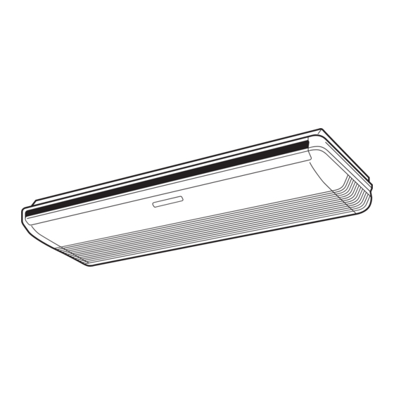
INDOOR UNIT (Ceiling type)
For authorized service personnel only.
INNENGERÄT (Decken-Typ)
Nur für autorisiertes Fachpersonal.
UNITÉ INTÉRIEURE (type plafonnier)
Pour le personnel agréé uniquement.
UNIDAD INTERIOR (tipo techo)
UNITÀ INTERNA (tipo a soffi tto)
UNIDADE INTERIOR (Tipo de tecto)
Apenas para técnicos autorizados.
MONTAJ KILAVUZU
İÇ ÜNİTE (Tavan tipi)
Yalnızca yetkili servis personeli için.
PART No. 9367702152
MADE IN THAILAND
[Original instructions]
Advertisement
Table of Contents

Subscribe to Our Youtube Channel
Related Manuals for AirStage AB A030GTEH Series


Summary of Contents for AirStage AB A030GTEH Series
- Page 1 INSTALLATION MANUAL INDOOR UNIT (Ceiling type) For authorized service personnel only. INSTALLATIONSANLEITUNG INNENGERÄT (Decken-Typ) Nur für autorisiertes Fachpersonal. MANUEL D’INSTALLATION UNITÉ INTÉRIEURE (type plafonnier) Pour le personnel agréé uniquement. MANUAL DE INSTALACIÓN UNIDAD INTERIOR (tipo techo) AB*A030GTEH Únicamente para personal de servicio autorizado. AB*A036GTEH MANUALE DI INSTALLAZIONE AB*A045GTEH...
-
Page 2: Table Of Contents
INSTALLATION MANUAL This mark indicates procedures which, if improperly performed, PART No. 9367702152 CAUTION might possibly result in personal harm to the user, or damage VRF system indoor unit (Ceiling type) to property. Read carefully all security information before use or install the air conditioner. Contents Do not attempt to install the air conditioner or a part of the air conditioner by yourself. -
Page 3: Accessories
2.3. Accessories 2.4. Optional parts WARNING The following options are available. Description Model Application For installation purposes, be sure to use the parts supplied by the manufacturer or other prescribed parts. The use of non-prescribed parts can cause serious accidents UTR-DPB24T Drain pump unit such as the unit falling, water leakage, electric shock, or fi... -
Page 4: Installation Dimension
3.3.2. Indoor unit installation 3.2. Installation dimension You can use the accessory template to help you install the indoor unit. The template helps Ceiling you determine the appropriate locations for suspension bolts and pipe openings (drain pipe and connection cable). INDOOR UNIT Drilling position for suspension bolt Ceiling... -
Page 5: Pipe Installation
3.3.6. Installing the indoor unit [For ④ Left rear piping, ⑤ Left piping] (1) Lift unit so that suspension bolts pass through the suspension fi ttings at the sides (4 • Transfer the Drain cap and Drain cap seal. places), and slide the unit back. Drain cap seal Drain cap Indoor unit... -
Page 6: Pipe Requirement
When using conventional (R22) fl are tools to fl are R410A pipes, the dimension A should CAUTION be approximately 0.5 mm more than indicated in the table (for fl aring with R410A fl are tools) to achieve the specifi ed fl aring. Use a thickness gauge to measure the dimension A. Improper pipe selection will degrade performance. -
Page 7: Installing Heat Insulation
Coupler heat insulation (Large) CAUTION (Accessories) Hold the torque wrench at its grip, keeping it at a right angle with the pipe, in order to tighten the fl are nut correctly. Connection pipe (Gas) Indoor unit When the fl are nut is tightened properly by your hand, hold the body side coupling with a Connection pipe (Small) (Liquid) separate spanner, then tighten with a torque wrench. -
Page 8: Electrical Wiring
(1) Install insulation for the drain pipe. (2) If “ ① Right rear piping”: fasten the drain hose with VT wire so that the pipe slopes Assemble as described below. correctly within the indoor unit. VT wire (Accessories) Drain hose Drain port Assemble Drain hose (Accessories) and Hose band Indoor unit (Rear view) -
Page 9: Electrical Requirement
6.2. Wiring method CAUTION Earth (Ground) the unit. Example Do not connect the earth (ground) cable to a gas pipe, water pipe, lightning rod, or a Outdoor unit or RB unit *1 telephone earth (ground) cable. Improper earthing (grounding) may cause electric shock. Transmission Do not connect power supply cables to the transmission or remote controller terminals, as this will damage the product. -
Page 10: Connection Of Wiring
6.4. Connection of wiring WARNING (1) Remove the 2 tapping screws and pull the control box downward. When using solid core cables, do not use the ring terminal. If you use the solid core cables with the ring terminal, the ring terminal’s pressure bonding may malfunction and cause the cables to abnormally heat up. -
Page 11: Optional Parts Wiring
Clamp 6.5. Optional parts wiring 6.5.1. Layout of the indoor unit PCB CN106 Power supply PCB CNB01 CNA01 CNA03 CNA02 Cable tie (locally purchased) Controller PCB 6.6. External input and external output (Optional parts) CNA04 (1) External input CNA05 • Indoor unit can be Operation/Stop, Emergency stop or Forced stop by using indoor unit PCB CNA01 or CNA02. - Page 12 ● Dry contact terminal ([CNA02], [CNA04]) [In the case of “Pulse” input] When a power supply is unnecessary at the input device you want to connect, use the Dry Connector Input signal Command contact terminal ([CNA02], [CNA04]). OFF → ON Emergency stop P.C.B CNA01 or CNA02...
-
Page 13: Field Setting
Operation behavior • If working in an environ- Table A ment where the wireless Rotary switch Rotary switch Connector Output voltage Status remote controller can be Address Address setting setting used, the addresses can Stop External output1 REF AD SW IU AD SW also be set using the Refrigerant... -
Page 14: Function Setting
Function 7.3. Function setting Function Setting number Default Details number 00 0°C • FUNCTION SETTING can be performed with the wired or wireless remote controller. 01 0.5°C (The remote controller is optional equipment) 02 1.0°C • Refer to the wired or wireless remote controller manual for detailed setting information. 03 1.5°C Choose the minimum temperature •... -
Page 15: Fresh-Air Intake
• Setting details [After completing “3.3. Installing the unit”…] (3) Connect the duct to the round fl ange. Function number Item Setting number (4) Seal with a band and vinyl tape, etc. so that air does not leak from the connection. Indoor unit address 00 to 63 Refrigeration address... -
Page 16: Check List
11. CHECK LIST 12. ERROR CODES Pay special attention to the check items below when installing the indoor unit(s). If you use a wired type remote controller, error codes will appear on the remote controller After installation is complete, be sure to check the following check items again. display.
Need help?
Do you have a question about the AB A030GTEH Series and is the answer not in the manual?
Questions and answers