Table of Contents
Advertisement
Quick Links
Advertisement
Table of Contents

Related Manuals for TRENDnet TEW-634GRU


Summary of Contents for TRENDnet TEW-634GRU
-
Page 2: Fcc Statement
FCC statement Federal Communication Commission Interference Statement This equipment has been tested and found to comply with the limits for a Class B digital device, pursuant to Part 15 of the FCC Rules. These limits are designed to provide reasonable protection against harmful interference in a residential installation. This equipment generates, uses and can radiate radio frequency energy and, if not installed and used in accordance with the instructions, may cause harmful interference to radio communications. - Page 3 Hereby, TRENDnet, declares that this TEW-634GRU is in compliance with the essential requirements and other relevant provisions of Directive 1999/5/EC. Por medio de la presente TRENDnet declara que el TEW-634GRU cumple con los requisitos esenciales y cualesquiera otras disposiciones aplicables o exigibles de la Directiva 1999/5/CE.
- Page 4 TRENDnet declara que este TEW-634GRU está conforme com os requisitos essenciais e Português [Portuguese] outras disposições da Directiva 1999/5/CE. Slovensko [Slovenian] TRENDnet izjavlja, da je ta TEW-634GRU v skladu z bistvenimi zahtevami in ostalimi relevantnimi določili direktive 1999/5/ES. TRENDnet týmto vyhlasuje, že TEW-634GRU spĺňa základné požiadavky a všetky Slovensky [Slovak] príslušné...
-
Page 5: Table Of Contents
TABLE OF CONTENT BOUT UIDE Purpose ... 1 Terms/Usage ... 1 Overview of this User’s Guide ... 1 ... 2 NTRODUCTION Applications: ... 2 Supported Features: ... 3 Wireless Performance Considerations ... 4 NPACKING AND ETUP Unpacking ... 5 Setup ... 5 ARDWARE NSTALLATION Front Panel ... - Page 6 Statistic ... 41 Wireless ... 42 Routing ... 43 Static ... 43 Dynamic ... 44 Routing Table... 45 Access ... 46 Filters ... 46 Virtual Server ... 49 Special AP ... 50 DMZ... 51 Firewall Settings ... 52 Management ... 53 Remote Management ...
-
Page 7: About This Guide
ABOUT THIS GUIDE Congratulations on your purchase of this 300Mbps Wireless N Gigabit Router with USB Port. This integrated access device combines Internet gateway functions with wireless LAN and Fast Ethernet switch. It provides a complete solution for Internet surfing and office resource sharing, and it is easy to configure and operate for every user. -
Page 8: Introduction
INTRODUCTION With the explosive growth of the Internet, accessing information and services at any time, day or night has become a standard requirement for most people. The era of the standalone PC is waning. Networking technology is moving out of the exclusive domain of corporations and into homes with at least two computers. -
Page 9: Supported Features
Supported Features: Wi-Fi compliant with IEEE 802.11n and IEEE 802.11b/g standards 4 x 10/100/1000Mbps Auto-MDIX LAN port and 1 x 10/100Mbps WAN port (Internet) Supports Cable/DSL modems with Dynamic IP, Static IP, PPPoE, PPTP, L2TP & BigPond connection types High-speed up to 300Mbps data rate using IEEE 802.11n connection 2 x 2dBi external antennas support high speed performance and great coverage with MIMO technology Support Wi-Fi Protected Setup (WPS) for easy connection... -
Page 10: Wireless Performance Considerations
Wireless Performance Considerations There are a number of factors that can impact the range of wireless devices. 1. Adjust your wireless devices so that the signal is traveling in a straight path, rather than at an angle. The more material the signal has to pass through the more signal you will lose. -
Page 11: Unpacking And Setup
Unpacking Open the box of the WLAN Router and carefully unpack it. The box should contain the following items: TEW-634GRU 300Mbps Wireless N Gigabit Router with USB Port CD ROM (Utility/User’s Guide) Multi-Language Quick Installation Guide 2 x 2dBi gain dipole antenna Power Adapter (12V DC, 2A) Cat. -
Page 12: Hardware Installation
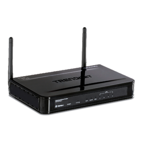
HARDWARE INSTALLATION Front Panel The figure below shows the front panel of the 300Mbps Wireless N Gigabit Router with USB Port. Front Panel POWER This indicator lights green when the hub is receives power, otherwise it is off. STATUS This indicator blinking green means the WLAN Router is working successfully. Otherwise, this indicator always on or off means the function of the WLAN Router has failed. -
Page 13: Rear Panel
Rear Panel The figure below shows the rear panel of the 300Mbps Wireless N Gigabit Router with USB Port. Rear Panel Antenna There are two 2dBi gain antennas on the rear panel for wireless connection. LAN (1-4) Four 10/100/1000Mbps Auto-MDIX LAN port for connecting to 10Mbps, 100Mbps Ethernet or 10000Mbps Gigabit connections. -
Page 14: Side Panel
Side Panel The figure below shows the side panel of the 300Mbps Wireless N Gigabit Router with USB Port. WPS (side panel) Push this button to execute the Wi-Fi Protected Setup process. Hanging Way User can mount the device on a wall. Mount the Nylon screw anchors into a cement wall and then drive a screw into the Nylon screw anchors. -
Page 15: Hardware Connections
Hardware connections Connecting the WLAN Router 1. Plug in one end of the network cable to the WAN port of the WLAN Router. 2. Plug in the other end of the network cable to the Ethernet port of the xDSL or Cable modem. -
Page 16: Pc Network Tcp/Ip Setting
PC NETWORK TCP/IP SETTING The network TCP/IP settings differ based on the computer’s operating system (Win95/98/ME/NT/2000/XP) and are as follows. Windows 95/98/ME 1. Click on the “Network neighborhood” icon found on the desktop. 2. Click the right mouse button and a context menu will be show. 3. -
Page 17: Windows 2000
6. Select “None” for the “Gateway address” field. Windows 2000 Double click on the “My Computer” icon on the desktop. When “My Computer” window opens, open the “Control Panel” and then open the “Network dialup connection” applet. Double click on the “Local area network connection” icon. Select “Properties”... -
Page 18: Windows Xp / Vista
Windows XP / Vista Point the cursor and click the right button on the “My Network Place” icon. Select “properties” to enter the TCP/IP setting window. 1. Set “IP address” to “Obtain an IP address automatically.” 2. Set “DNS” to “Obtain DNS server address automatically.”... -
Page 19: Configuration
CONFIGURATION First make sure that the network connections are functioning normally. This WLAN Router can be configured using Internet Explorer 5.0 or newer web browser versions. Login to the WLAN Router through Wireless LAN Before configuring the WLAN Router through WLAN, make sure that the SSID, Channel and the WEP is set properly. -
Page 20: Setup Wizard
Setup wizard is provided as part of the web configuration utility. Users can simply follow the step-by-step process to get the wireless Router configuration ready to run in 6 easy steps by clicking on` the “Wizard” button on the function menu. The following screen will appear. - Page 21 Step 3: Set LAN connection and DHCP server Set user’s IP address and mask. The default IP is 192.168.10.1. If the user chooses to enable DHCP, please click “Enable”. DHCP enabled is able to automatically assign IP addresses. Please assign the range of IP addresses in the fields of “Range start”...
- Page 22 If the user has enabled DHCP server, choose "Obtain IP automatically (DHCP client)" to have the WLAN Router assign IP addresses automatically. Fixed IP Address:...
- Page 23 If the Internet Service Provider (ISP) assigns a fixed IP address, choose this option and enter the assigned WAN IP Address, WAN Subnet Mask, WAN Gateway Address and DNS Server Addresses for the WLAN Router. PPPoE to obtain IP automatically:...
- Page 24 If connected to the Internet using a PPPoE (Dial-up xDSL) connection, and the ISP provides a User Name and Password, then choose this option and enter the required information.
- Page 25 PPPoE with a fixed IP address: If connected to the Internet using a PPPoE (Dial-up xDSL) connection, and the ISP provides a User Name, Password and a Fixed IP Address, choose this option and enter the required information.
- Page 26 PPTP: If connected to the Internet using a PPTP xDSL connection, enter your IP, Subnet Mask, Gateway, Server IP, PPTP Account and PPTP Password.
- Page 27 L2TP: If connected to the Internet using a L2TP (Dial-up xDSL) connection and the ISP provides a Server IP, Account and Password information, choose this option and enter the required information.
- Page 28 Big Pond Cable(Australia): If your ISP is Big Pond Cable, the ISP will provide a User Name, Password, Authentication Server and Login Server IP (Optional). Choose this option and enter the required information.
- Page 29 Russia PPPoE: If your ISP is Russian PPPoE, the ISP will provide a User Name, Password. If you have a Static IP WAN Physical IP Address, WAN Physical Subnet Mask and WAN Physical Gateway IP Address will be required. Choose this option and enter the required information.
- Page 30 Russia PPTP: If connected to the Internet using Russian PPTP xDSL connection, enter your server IP, PPTP Account and Password. If using Static IP you must enter your IP, Subnet Mask, Gateway, Server IP, PPTP Account and PPTP Password.
- Page 31 Russia L2TP: If connected to the Internet using Russian L2TP (Dial-up xDSL) enter your server IP, PPTP Account and Password. If using Static IP you must enter your IP, Subnet Mask, Gateway, Server IP, PPTP Account and PPTP Password.
- Page 32 Step 5: Set Wireless LAN connection Click “Enable” to enable Wireless LAN. If user enables the Wireless LAN, type the SSID in the text box and select a channel. The SSID and channel must be the same as wireless devices attempting to connect to the WLAN Router. Step 6: Setup completed The Setup wizard is now completed.
-
Page 33: Advanced Configuration
Host Name: Type the host name in the text box. The host name is required by some ISPs. The default host name is "TEW-634GRU" IP Address: This is the IP address of the WLAN Router. The default IP address is 192.168.10.1. -
Page 34: Wan
All DHCP client computers are listed in the table at the bottom of the screen, providing the host name, IP address, and MAC address of the client. Start IP: Type an IP address to serve as the start of the IP range that DHCP server will use to assign IP addresses to all LAN devices connected to the WLAN Router. -
Page 35: Password
WAN IP: Select whether user wants to specify an IP address manually, or want to obtain an IP address automatically. When Specify IP is selected, type the IP address, subnet mask, and default gateway in the text boxes. User’s ISP will provide with this information. -
Page 36: Time
Time This screen enables users to set the time and date for the WLAN Router's real-time clock, select properly time zone, and enable or disable daylight saving. Local Time: Displays the current time applied on the WLAN Router. Time Zone: Select the time zone from the drop-down list. Synchronize the clock with: Select the clock adjustment method form the drop- down list. -
Page 37: Dynamic Dns
Dynamic DNS This synchronizes the DDNS server with your current Public IP address when you are online. First, you need to register your preferred DNS with the DDNS provider. Then, please select the DDNS address in the Server Address and fill the related information in the below fields: Host Name, User Name and Password. - Page 38 Enable/Disable: Enables or disables wireless LAN on the WLAN Router. SSID: Type an SSID in the text box. The SSID of any wireless device must match the SSID typed here in order for the wireless device to access the LAN and WAN of the WLAN Router.
-
Page 39: Security
Security Authentication Type: The authentication type is set to Disable by default. There are four options: Disabled, WEP, WPA, WPA2 and WPA-Auto. WEP Encryption WEP: Open System and Shared Key requires the user to set a WEP key to exchange data with other wireless clients that have the same WEP key.. Mode: Select the key type: ASCII or HEX... - Page 40 WEP Key: Select the level of encryption from the drop-down list. The WLAN Router supports, 64 and 128-bit encryption. Key 1 ~ Key 4: Enables users to create up to 4 different WEP keys. Manually enter a set of values for each key. Select a key to use by clicking the radio button next to the key.
- Page 41 RADIUS Server: 1. Enter the IP address, Port used and Shared Secret by the Primary Radius Server. 2. Enter the IP address, Port used and Shared Secret by the Secondary Radius Server. (optional)
-
Page 42: Advanced
WPA-PSK/WPA2-PSK Security If WPA, WPA2 or WPA-Auto PSK is selected the below screen will show. Cipher Type: Select the cipher type for TKIP or AES encryption, Select Auto for auto detects the cipher type. Passphrase: Enter a passphrase key, the length should be 8 characters at least. Advanced This screen enables users to configure advanced wireless functions. -
Page 43: Wi-Fi Protected Setup
Beacon Interval: Type the beacon interval in the text box. User can specify a value from 25 to 1000. The default beacon interval is 100. RTS Threshold: Type the RTS (Request-To-Send) threshold in the text box. This value stabilizes data flow. If data flow is irregular, choose values between 256 and 2346 until data flow is normalized. -
Page 44: Status
Push Button Configuration: Clicking this button will invoke the Push Button Configuration (PBC) method of WPS. It is only used when WLAN Router acts as a Registrar. This feature can also be used by pressing the WPS button on the side of the WLAN Router. -
Page 45: Log
WAN: This section displays the WAN interface configuration including the MAC address, Connection status, DHCP client status, IP address, Subnet mask, Default gateway, and DNS. Wireless: This section displays the wireless configuration information, including the MAC address, the Connection status, SSID, Channel and Authentication type. LAN: This section displays the LAN interface configuration including the MAC address, IP Address, Subnet Mask, and DHCP Server Status. -
Page 46: Log Setting
Time: Displays the time and date that the log entry was created. Message: Displays summary information about the log entry. Log Setting This screen enables users to set Router Log parameters. SMTP Authentication: Select Enabled SMTP server authentication. SMTP Account: If the SMTP Authentication enabled, fill in the SMTP account name here. -
Page 47: Statistic
Syslog Server: Type the IP address of the Syslog Server if user wants the WLAN Router to listen and receive incoming Syslog messages. Log Type: Enables users to select what items will be included in the log: System Activity: Displays information related to WLAN Router operation. Debug Information: Displays information related to errors and system malfunctions. -
Page 48: Wireless
Wireless This screen enables users to view information about wireless devices that are connected to the WLAN Router. Connected Time: Lists all wireless clients and how long they have been connected WLAN Router. MAC Address: Displays the wireless client’s MAC address. -
Page 49: Routing
Routing This selection enables users to set how the WLAN Router forwards data: Static and Dynamic. Routing Table enables users to view the information created by the WLAN Router that displays the network interconnection topology. Static It enables users to set parameters by which the WLAN Router forwards data to its destination if the network has a static IP address. -
Page 50: Dynamic
Dynamic This screen enables users to set NAT parameters. Transmit: Click the radio buttons to set the desired transmit parameters, Disabled, RIP 1, or RIP 2. Receive: Click the radio buttons to set the desired transmit parameters, Disabled, RIP 1, or RIP 2. -
Page 51: Routing Table
Routing Table This displays the routing table of the WLAN Router. The routing table is a database created by the WLAN Router that displays the network interconnection topology. Network Address: Displays the network IP address of the connected node. Network Mask: Displays the network (subnet) mask of the connected node. Gateway Address: Displays the gateway address of the connected node. -
Page 52: Access
Access This page defines access restrictions, set up protocol and IP filters, create virtual servers, access for special applications such as games, and set firewall rules. Filters Using filters to deny or allow the users to access. Five types of filters to select: MAC, URL blocking, IP, Protocol filter and Domain blocking. - Page 53 MAC Address: Type the MAC address of the user's network interface. Add: Click to add the user to the list at the bottom of the page. Update: Click to update information for the user, if you have changed any of the fields.
- Page 54 IP Filters This screen enables you to define a minimum and maximum IP address range filter; all IP addresses falling within the range are not allowed Internet access. The IP filter profiles are listed in the table at the bottom of the page. (Note: Click anywhere in the item.
-
Page 55: Virtual Server
Cancel: Click the Cancel button to erase all fields and enter new information. Virtual Server This screen enables users to create a virtual server via the WLAN Router. If the WLAN Router is set as a virtual server, remote users requesting Web or FTP services through the WAN are directed to local servers in the LAN. -
Page 56: Special Ap
Public Port: Type the port number on the WAN that will be used to provide access to the virtual server. LAN Server: Type the LAN IP address that will be assigned to the virtual server. Add: Click to add the virtual server to the table at the bottom of the screen. Update: Click to update information for the virtual server if the user has selected a listed item and has made changes. -
Page 57: Dmz
Name: Type a descriptive name for the application. Trigger: Defines the outgoing communication that determines whether the user has legitimate access to the application. ● Protocol: Select the protocol (TCP, UDP, or ICMP) that can be used to access the application. ●... -
Page 58: Firewall Settings
Enable: Click to enable or disable the DMZ. DMZ Host IP: Type a host IP address for the DMZ. The computer with this IP address acts as a DMZ host with unlimited Internet access. Apply: Click to save the settings. Firewall Settings This screen enables users to set up the firewall. -
Page 59: Management
Enable: Click to enable or disable the firewall rule profile. Name: Type a descriptive name for the firewall rule profile. Action: Select whether to allow or deny packets that conform to the rule. Source: Defines the source of the incoming packet that the rule is applied to. ●... - Page 60 HTTP: Enables users to set up HTTP access for remote management. Allow to Ping WAN Port: Type a range of Router IP addresses that can be pinged from remote locations UPnP Enable: UPnP is short for Universal Plug and Play that is a networking architecture that provides compatibility among networking equipment, software, and peripherals.
-
Page 61: Tools
Tools This page enables users to restart the system, save and load different settings as profiles, restore factory default settings, run a setup wizard to configure WLAN Router settings, upgrade the firmware, and ping remote IP addresses. Restart Click “Restart” to restart the system in the event the system is not performing correctly. -
Page 62: Settings
Settings This screen enables users to save settings as a profile and load profiles for different circumstances. User can also load the factory default settings, and run a setup wizard to configure the WLAN Router and Router interface. Save Settings: Click “Save” to save the current configuration as a profile that can load when necessary. -
Page 63: Firmware
Firmware This screen enables users to keep the WLAN Router firmware up to date. Please follow the below instructions: Download the latest firmware from the manufacturer's Web site, and save it to disk. Click “Browse” and go to the location of the downloaded unzipped firmware file. Select the file and click “Upgrade”... -
Page 64: Ping Test
Ping Test The ping test enables users to determine whether an IP address or host is present on the Internet. Type the host name or IP address in the text box and click Ping. -
Page 65: Usb Control Center Utility
WLAN Router. The utility allows you to use USB devices as if they were connected directly to your PC through the Wireless N Gigabit Router with USB port (TEW-634GRU). System Select this feature to completely close and exit from USB Control Center utility. -
Page 66: Print Sharing
Configure Server Click this button to configure the USB server and to log into the user interface of the Wireless N Gigabit Router with USB port (TEW-634GRU). Print Sharing This section describes how to use a USB printer through the WLAN Router. Note: For proper installation it is recommended that the printer’s drivers are installed... -
Page 67: Network Scanner
Network Scanner This section describes the usage of a scanner through the Wireless N Gigabit Router with USB port. Once you click on the Network Scanner button on the USB utility the below image will appear. Paper Source: Select the type of scanner being used (Flatbed or Document Feeder) Type of image: For proper scanning select the appropriate type of file being scanned. -
Page 68: Connecting Usb Storage Device
Name: Type the name of the folder you would like to have the scanned images stored in. File Format: Select the file format Save Location: Click Browse and select the location where you would like to have the scanned files saved in. Back: Click to return to tbe previous screen. - Page 69 Connect Click this button to establish connection to the selected USB device that is not configured to Auto-Connect, like USB storage devices. Disconnect Click this button to properly disconnect your computer form the connected USB device. Request to Connect Click this button if the USB device you would like to connect to is already connected by another computer in your network.
-
Page 70: Technical Specifications
TECHNICAL SPECIFICATIONS Hardware Wired: IEEE 802.3/u Fast Ethernet, IEEE 802.3ab Gigabit Ethernet Standards Wireless: IEEE 802.11b, IEEE 802.11g, IEEE 802.11n (draft 2.0), IEEE 802.11e QoS USB: v1.0, 1.1, 2.0 1 x 10/100Mbps Auto-MDIX port (Internet) 4 x 10/100/1000Mbps Auto-MDIX ports WPS Button Enable Wi-Fi Protected Setup function 1 x USB 2.0, 1.1 Compliant USB Type A Port... -
Page 71: Limited Warranty
Limited Warranty TRENDnet warrants its products against defects in material and workmanship, under normal use and service, for the following lengths of time from the date of purchase. AC/DC Power Adapter, Cooling Fan, and Power Supply carry 1 year warranty. If a product does not operate as warranted during the applicable warranty period, TRENDnet shall reserve the right, at its expense, to repair or replace the defective product or part and deliver an equivalent product or part to the customer. The repair/replacement unit’s warranty continues from the original date of purchase. All products that are replaced ... - Page 72 AT TRENDNET’S OPTION. THIS DISCLAIMER OF LIABILITY FOR DAMAGES WILL NOT BE AFFECTED IF ANY REMEDY PROVIDED HEREIN SHALL FAIL OF ITS ESSENTIAL PURPOSE. Governing Law: This Limited Warranty shall be governed by the laws of the state of California. Some TRENDnet products include software code written by third party developers. These codes are subject to the GNU General Public License ("GPL") or GNU Lesser General Public License ("LGPL"). Go to http://www.trendnet.com/gpl or http://www.trendnet.com Download section and look for the desired TRENDnet product to access to the GPL Code or LGPL Code. These codes are distributed WITHOUT WARRANTY and are subject to the copyrights of the developers. TRENDnet does not provide technical support for these codes. Please go ...
Need help?
Do you have a question about the TEW-634GRU and is the answer not in the manual?
Questions and answers